Is testing them simply a matter of sending a few amps through some resistors and looking for ripple/voltage drops/excess heat?
They're rated for 7.5 A, so I'd run 7.5 A through them at the expected drop-out voltage in the target application. Do that for an hour and see what happens.
Alternatively, include them in your amp design and run the amp for an hour loaded with a dummy load using a sine wave at clipping levels. If the regulator survives that, it'll survive music signal as well.
Tom
Thanks Tom, for looking into the powersupply module. And thank you HAL2010, for introducing it. I've ordered two, doesn't cost much to try, and I rather like the idea of reusing IC's.
So, the regs arrived today. I've been running between 4 and 6A out of them (the limit of my power supply) out of one for the last half hour and aside from getting ungodly hot (4A stabilized at 90 degrees C and 6A hit 110 degrees before I switched it off), they work beautifully with only 2mv of ripple.
Glad to help.
When you wire the regulators to the ChipAmps try using some heavy gauge flat copper braid in insulation for the runs. This lowers the resistance and inductance and increases the capacitance. The LT1083 has very low output impedance, so you do not want to loose that performance with small wiring.
When you wire the regulators to the ChipAmps try using some heavy gauge flat copper braid in insulation for the runs. This lowers the resistance and inductance and increases the capacitance. The LT1083 has very low output impedance, so you do not want to loose that performance with small wiring.
Just to ensure I'm not being stupid, I want to check calculations of what size smoothing capacitor I will need. I figure it's about time I relearned all the stuff I used to know when I did an electrical engineering diploma almost 10 years ago.
With 24V secondaries, that will give me ((24x1.414)-(1.5x2))=~32.3V assuming a perfect smoothing capacitor and a total of 3V drop across 2xMUR60's. If I need (30+1.5)=31.5v at the regulator at all times, that would mean I can have 0.8V of maximum ripple.
Assuming 5A constant output (probably high), 0.8V of ripple and 100Hz post-rectification frequency, the minimum smoothing capacitor I need is C = 0.8 * I /(ΔV * F) = 0.8 * 5A /(1.6Vp-p * 100hZ) = 25000µf - does this seem correct? With a constant 2.5A draw, that drops to 12000uf. I'm not sure what sort of current would be 'typical' so I am overdesigning everything here.
Last edited:
You took ten years to forget, I can do much better. I can forget things in under 5 minutes.................I figure it's about time I relearned all the stuff I used to know when I did an electrical engineering diploma almost 10 years ago.................
My record is walking between rooms and when I get there, can't remember what I came for !!!!!
I do not see anything wrong with the logic.
I was using just the 4700uF/50VDC caps from the regulator kit with very good results and very quiet amps with the LM1875's with single ended inputs. The idle current draw was ~30mA, so those will work.
The regulator boards come with 4700uF caps after the bridge rectifier. If you leave off the diode rectifiers, you can use the Gainclone rectifier/cap board with 18000uF/50VDC caps on it to add the extra capacitance for keeping the ripple low at the larger current draws. That would add significantly to the transient capability of the amp output.
May still try this with my moded LM3875TF amp boards and see what happens.
I use ±20mF for an 8ohms rated amplifier and recommend ±40mF for a 4ohms rated amplifier when both are for full range including driving a bass with 20Hz when it's available.
I do not see anything wrong with the logic.
I was using just the 4700uF/50VDC caps from the regulator kit with very good results and very quiet amps with the LM1875's with single ended inputs. The idle current draw was ~30mA, so those will work.
The regulator boards come with 4700uF caps after the bridge rectifier. If you leave off the diode rectifiers, you can use the Gainclone rectifier/cap board with 18000uF/50VDC caps on it to add the extra capacitance for keeping the ripple low at the larger current draws. That would add significantly to the transient capability of the amp output.
May still try this with my moded LM3875TF amp boards and see what happens.
I was going to just shoehorn a bigger cap and the MUR860's on there but that's actually a great idea
As I know for ripple you need 10kuF for 1V ripple for 1A (at 50Hz).
So you would need around 60kuF for 5A 0,8V.
Plus network voltage is not always stable. It can go down a lot.
So you would need around 60kuF for 5A 0,8V.
Plus network voltage is not always stable. It can go down a lot.
I got the LT1083 regs today, don't have time to put them together now, but I checked them compared to the datasheet for LT1083 and this page:
http://www.tnt-audio.com/gif/schem_lm317_layout.gif .
Seems the ebay kit is like the circuit on the left, which is a bad layout, on the right is the better layout:
So, thinking of cutting the pcb track and wiring it differently, see pic, use a bigger Cadj, maybe 47uF, 25uF is recommended in the datasheet for ripple at 120Hz, and maybe not use the ceramic cap on the output pin.
Anything look/sound wrong?
Attachments
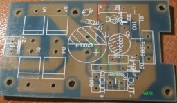
It all looks terribly wrong to me. Shown is an LM117, not a LT1083. Where is the diode bridge to rectify the AC? What purpose are the 1 ohm resistors?
I got the LT1083 regs today, don't have time to put them together now, but I checked them compared to the datasheet for LT1083 and this page:
http://www.tnt-audio.com/gif/schem_lm317_layout.gif .
Seems the ebay kit is like the circuit on the left, which is a bad layout, on the right is the better layout:
So, thinking of cutting the pcb track and wiring it differently, see pic, use a bigger Cadj, maybe 47uF, 25uF is recommended in the datasheet for ripple at 120Hz, and maybe not use the ceramic cap on the output pin.
Anything look/sound wrong?
Why 'fix' something that's not broken? The pictured circuit is solely with creating an intended regulator output impedance (according from the page it's on). From what I understand, that's not an issue with the LT1083
Sorry, link was wrong, this is right:
Simple Voltage Regulators Part 2: Output Impedance
It explains the circuit. The 1 ohms just simulate ground wire. So probably not such a big difference, but I'd like to get it done right. If you check the datasheet:
http://cds.linear.com/docs/en/datasheet/108345fh.pdf
You'll see the same recommended layout on page 12, Figure 2, its not just for lm317.
And I agree, if it aint broke, why fix it, but I cant help myself, when I know just a few small changes should make it better.
"the minimum smoothing capacitor I need is C = 0.8 * I /(ΔV * F)"
"for ripple you need 10kuF for 1V ripple for 1A (at 50Hz)"
WHERE did you fellas get these formulas??
"for ripple you need 10kuF for 1V ripple for 1A (at 50Hz)"
WHERE did you fellas get these formulas??
"the minimum smoothing capacitor I need is C = 0.8 * I /(ΔV * F)"
"for ripple you need 10kuF for 1V ripple for 1A (at 50Hz)"
WHERE did you fellas get these formulas??
Capacitor Input Filter Calculation
I used 0.8 for the fudge factor instead of 0.7. I vaguely remember this formula from EE days too. No idea where the second calculation came from but it seems very high
I viewed the article at
Capacitor Input Filter Calculation
and I believe that will perhaps give the absolute minimum capacitance needed to keep the voltage regulator operating within specification. However, there are some oversights---for his example of a 9 volt supply using a 12 volt transformer, he uses 12v as the rectified voltage in his calculation. This is incorrect--- a 12v transformer will produce ~17 volts of DC (12 x √2); this would change his minimum needed capacitance to 318uF, according to his own formulas. This is woefully low, in my opinion and experience; so it's hard to give much credence to his figures.
I viewed the article at
Capacitor Input Filter Calculation
and I believe that will perhaps give the absolute minimum capacitance needed to keep the voltage regulator operating within specification. However, there are some oversights---for his example of a 9 volt supply using a 12 volt transformer, he uses 12v as the rectified voltage in his calculation. This is incorrect--- a 12v transformer will produce ~17 volts of DC (12 x √2); this would change his minimum needed capacitance to 318uF, according to his own formulas. This is woefully low, in my opinion and experience; so it's hard to give much credence to his figures.
Do you have a better method for calculating smoothing capacitors?
Well, no, I don't have a better electronic formula for calculating; so I defer to his method to give the absolute minimum amount of capacitance needed. What I use has more to do with economics; i.e., I figure out how much I can afford and buy the biggest, best electrolytic capacitor I can find that will fit in the allotted space and handle the appropriate voltage. Not exactly scientific, mind you, but it works for me.
I see many using 1mF per Ampere of output current as an absolute minimum of smoothing capacitance.
Double this to 2mF/A for reasonable output ripple.
Double again to 4mF/A for low output ripple.
And try 10mF/A for ultra low output ripple, where rCRC is not acceptable.
Double this to 2mF/A for reasonable output ripple.
Double again to 4mF/A for low output ripple.
And try 10mF/A for ultra low output ripple, where rCRC is not acceptable.
- Status
- Not open for further replies.
- Home
- Amplifiers
- Chip Amps
- Just another Gainclone Build