I would include the output section into the op amp feedback loop.
That would leave only tube sound.
That would leave only tube sound.
Hey- Glad you're back!
I am liking the simplified version. Sorry it looks so much like ESP's headphone amp but with germanium, but it's a classical topology that works well. I am enjoying our conversation so I would like to touch on a few points for academic purposes at least (since this is your final version)
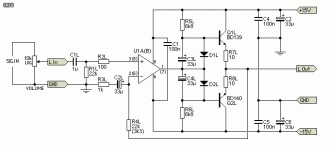
I'll refer back to the discussion on Rod's headphone amp again- There is frustratingly little ability to dial in the bias current in Rod's design (attached below just for quick reference), he just depends upon the 1N4148 bias diodes D1 and D2 to have a slightly higher forward drop than the transistors, and has some adjustability with R5/R6 to set the diode current, keeping it above about 2mA. I am unsure how the 1N34A forward drop compares to that of the output transistors- that will be important to breadboard and check very early. With respect to the emitter resistors R8 and R9, in Rod's design he indicates that the 10 ohm values can be increased as high as 22 ohms, it will reduce the available output power but won't affect output impedance, but will reduce the amount of current that can be drawn by the load. I can attest that with the 1N4148 devices for bias on these BD139/140, and 10 Ohm emitter resistors there is LOTS of power, and zero (audibly) detected crossover distortion. Again, your mileage may vary- I'm interested to know how the 1N34's do. At least you have the option of increasing the emitter resistors if needed to reduce bias current. I also assert that the output devices only really need to be slightly on to eliminate crossover distortion, because the op-amp has such high open loop gain and fast slew rate it can cross a small dead gap without it being audible. I prefer the devices be on a little further, maybe at least 10mA? bias current, but any more than that seems just a waste and can cause thermal problems. I like the battery powered idea, so less is more when it comes to this quiescent current.
Yes, you can power both stages on the same supply. Rod indicates an unregulated supply can be used, but does not recommend it (I think) just because some who build the amp will use the high gain value and I expect some hum would be possible. Rod seems more concerned about the non-linear current consumption of the output stage messing with a possible upstream pre-amp. Fortunately the op-amp has really excellent power supply rejection ratio, and even if there were relatively large ripple on the supply rails, the op-amp would just drive the outputs harder at times to compensate and still manage to produce a low noise low distortion copy of the input. Ripple is well within the pass band of the amplifier so it should be as easily cancelled as the signal amplified.
When I built my copy of Rod's design I went straight to proto/vero board. I was a little spooked about oscillation, and the design was so mature only minor revisions if any would be needed in the future (likely just the feeback gain resistor). I have included a bunch of photos below.
First, my build of the 113 headphone amp in an old metal router box. It was a prototype (of my layout), and wanted to be able to drive small speakers with it hence the binding posts. Shown also is my braided vacuum cleaner wire power lead with color coded RCA plugs. I did not like the requirement for a vertical heatsink so I attached the transistors to the underside using the box as the heatsink. BTW the little brown resistors are the 10 Ohm ceramic 1W if you can believe that, no bigger than 1/4W carbon. I used them for the Zobel as well. I did not have room for big resistors in this layout.


Here are the layout sketches I did on grid paper if you are interested. I was trying to be extra careful about out to in coupling yet I made it pretty dense. Ground ring around the outside, +/-15V in the center, opposing outputs with fairly good mirror symmetry. It works great, no oscillation, extremely clean, tons of power for a headphone or small test amp.


This is my ESP project #06 RIAA Phono Pre-amp using the same braided power lead. It's an exceptionally good phono preamp design he has there- Far superior to any of the typical one-op-amp designs. An interesting and informative read for sure.

Here is my ammo can +/-15V @ 1A power supply. I was lucky enough to have a medium size 14V-0-14V toroidal transformer from a computer subwoofer and most of the other parts in my junk box. The entire supply is built on a thick aluminum plate that was slid down into the box and bolted through the side of the box. Loosely based upon ESP project #05 as far as the LM338/LM337 setup with protection diodes, with the regulators heatsinked to the big aluminum plate. I broke the bulk bypass capacitors into a smaller first bank, and larger second bank with spare ceramic emitter resistors adding up to 1 Ohm between the two banks to help reduce RMS current from the transformer (hum and heating), inrush current, and greatly reduces ripple going into the regulators. It's super clean and quiet. It has two power LED's so I can verify both supplies are up, and can run 4 op-amp based accessories at a time with no worries about shorting outputs. (Just need to make sure everything is off, and plug red into red etc . . .)


Anyway, keep me posted! -W
I am liking the simplified version. Sorry it looks so much like ESP's headphone amp but with germanium, but it's a classical topology that works well. I am enjoying our conversation so I would like to touch on a few points for academic purposes at least (since this is your final version)
For the resistor values chosen for R8, R9 of 0.22R: The circuit's quiescent current is determined by the voltage across the diodes (1N34A) and emitter resistors (R8 and R9). Increasing R8 and R9 from 0.22R to 10R would drastically reduce the quiescent current, likely introducing significant crossover distortion. The value should be correct, but it could be increased to around ~0.47R to slightly increase thermal stability, while minimizing crossover distortion.
I'll refer back to the discussion on Rod's headphone amp again- There is frustratingly little ability to dial in the bias current in Rod's design (attached below just for quick reference), he just depends upon the 1N4148 bias diodes D1 and D2 to have a slightly higher forward drop than the transistors, and has some adjustability with R5/R6 to set the diode current, keeping it above about 2mA. I am unsure how the 1N34A forward drop compares to that of the output transistors- that will be important to breadboard and check very early. With respect to the emitter resistors R8 and R9, in Rod's design he indicates that the 10 ohm values can be increased as high as 22 ohms, it will reduce the available output power but won't affect output impedance, but will reduce the amount of current that can be drawn by the load. I can attest that with the 1N4148 devices for bias on these BD139/140, and 10 Ohm emitter resistors there is LOTS of power, and zero (audibly) detected crossover distortion. Again, your mileage may vary- I'm interested to know how the 1N34's do. At least you have the option of increasing the emitter resistors if needed to reduce bias current. I also assert that the output devices only really need to be slightly on to eliminate crossover distortion, because the op-amp has such high open loop gain and fast slew rate it can cross a small dead gap without it being audible. I prefer the devices be on a little further, maybe at least 10mA? bias current, but any more than that seems just a waste and can cause thermal problems. I like the battery powered idea, so less is more when it comes to this quiescent current.
Neither the op-amp nor the output transistors can tell the difference between +/- rails with ground bias or a single ended supply with a virtual ground. If your R1 were tied to a well bypassed virtual ground divider at VDD/2 and the supply single ended, (and your output cap back in place after feedback) no other changes would be necessary and the op-amp and output devices would behave exactly the same with no clue. The op-amp would drive the final output to VDD/2 to keep the V- input the same voltage as the V+ input. (the advantage of DC feedback and using an op-amp) The output transistors would have no clue and no change to their operating points would occur. The relative voltage differences between their terminals would be identical with the output sitting at VDD/2. Again, I'm a "minimal capacitors in the audio path" kind of guy, so I did not mind building a supply twice as complicated to be able to eliminate them. The output will be at ground in your design, no question. The op-amp will use the full force of it's open loop gain to guarantee that, so long as your output transistors do not rail and saturate at one extreme because of some major imbalance problem.As for the power rails, I've worked on worse things. They could run on 12V+ with a virtual ground at mid supply, This could be done. However, the AC187/AC188 output stage relies on symmetrical voltage swing for proper biasing and thermal stability. A single-ended supply shifts the quiescent bias point to 6V instead of 0V, affecting how the transistors operate. If the Germanium pair needs +/- rails, why not do the same for the entire circuit? The OPA2134 could run on 9V+/-, but it may reduce dynamic range a little bit on high energy passages if the amp is driven hard.
There will be no voltage on the output, guarantee it.Here's the simplified version, If there's little to no DC voltage at the output, we can omit C6 and R10. I think at 9V+/-, the Germaniums should remain stable with adequate heatsinks and thermal drift leading to any DC bias getting through should be no concern.
We can power the gain and buffer stage on shared, decoupled rails. This may increase crosstalk a little bit, but I don't think it would be too noticeable.
Given the simple power supply, this could easily be a portable AC or battery powered headphone amp
Yes, you can power both stages on the same supply. Rod indicates an unregulated supply can be used, but does not recommend it (I think) just because some who build the amp will use the high gain value and I expect some hum would be possible. Rod seems more concerned about the non-linear current consumption of the output stage messing with a possible upstream pre-amp. Fortunately the op-amp has really excellent power supply rejection ratio, and even if there were relatively large ripple on the supply rails, the op-amp would just drive the outputs harder at times to compensate and still manage to produce a low noise low distortion copy of the input. Ripple is well within the pass band of the amplifier so it should be as easily cancelled as the signal amplified.
When I built my copy of Rod's design I went straight to proto/vero board. I was a little spooked about oscillation, and the design was so mature only minor revisions if any would be needed in the future (likely just the feeback gain resistor). I have included a bunch of photos below.
First, my build of the 113 headphone amp in an old metal router box. It was a prototype (of my layout), and wanted to be able to drive small speakers with it hence the binding posts. Shown also is my braided vacuum cleaner wire power lead with color coded RCA plugs. I did not like the requirement for a vertical heatsink so I attached the transistors to the underside using the box as the heatsink. BTW the little brown resistors are the 10 Ohm ceramic 1W if you can believe that, no bigger than 1/4W carbon. I used them for the Zobel as well. I did not have room for big resistors in this layout.
Here are the layout sketches I did on grid paper if you are interested. I was trying to be extra careful about out to in coupling yet I made it pretty dense. Ground ring around the outside, +/-15V in the center, opposing outputs with fairly good mirror symmetry. It works great, no oscillation, extremely clean, tons of power for a headphone or small test amp.
This is my ESP project #06 RIAA Phono Pre-amp using the same braided power lead. It's an exceptionally good phono preamp design he has there- Far superior to any of the typical one-op-amp designs. An interesting and informative read for sure.
Here is my ammo can +/-15V @ 1A power supply. I was lucky enough to have a medium size 14V-0-14V toroidal transformer from a computer subwoofer and most of the other parts in my junk box. The entire supply is built on a thick aluminum plate that was slid down into the box and bolted through the side of the box. Loosely based upon ESP project #05 as far as the LM338/LM337 setup with protection diodes, with the regulators heatsinked to the big aluminum plate. I broke the bulk bypass capacitors into a smaller first bank, and larger second bank with spare ceramic emitter resistors adding up to 1 Ohm between the two banks to help reduce RMS current from the transformer (hum and heating), inrush current, and greatly reduces ripple going into the regulators. It's super clean and quiet. It has two power LED's so I can verify both supplies are up, and can run 4 op-amp based accessories at a time with no worries about shorting outputs. (Just need to make sure everything is off, and plug red into red etc . . .)
Anyway, keep me posted! -W
Attachments
@stocktrader200 The output section already has a feedback loop to input of the Op Amp. This actually makes the circuit more linear and reduces distortion. Depending on the resistance in this network, it can retain or reduce some of the 2nd order harmonic distortion that many people liken to “tube sound”. My opinion is that Germanium designs do not sound like vacuum tube designs, although they both share some common distortion and soft clipping characteristics.
Last edited:
@wparks Your projects look great! I like your resourcefulness for finding project enclosures, like the ammo box PSU. The enclosure used for your ESP RIAA Phono Pre-amp looks like some Budd enclosures I had at one time.
Your 113headphone amp build looks really clean, I really like the quality of your hand drawing and the protyping board looks like a very well executed build. The ground ring around the parameter of the board likely lends to a very clean sound quality. I see no reason to develop a PCB, based on the stability of your build. 👍
As for my headphone amp design, I'll likely build the 113 as well. Thank you very much for introducing it to me and for sharing your build.
I'm also working on a small ~1W stereo amp design for computer speakers. It will be based on a Realistic SA-10, but it will be highly modernized for very clean, linear sound with high dynamic range. It will be in a new post fairly soon.
I have an interesting build worth noting:
This is a "Conrad Johnson PV-12" 12AU7 preamplifier kit and 2x JLH1969 10W 2N3055 amplifiers. Of course, it has been stuffed into an old EICO O-scope.
