maxpou said:Hi 5th element,
check on this post i have many problem with same PS. you have diodes on pin 2 and 3, i removed these diodes and all is OK.
http://www.diyaudio.com/forums/showthread.php?threadid=78162&perpage=10&pagenumber=3
Maxpou
Thanks for the idea. As the AD797 has these diodes built in I did disconnect the diodes over pin 2 and 3, but nothing changed.
I have read lots of things about preserving the bridge and such, with a reasonable explanation from Andrew, in the thread you linked. Right off the bat it made 'no sense' heh 😛 probably because I couldn't form a mental picture when reading it. So with a bit of time and paper, I hope I will be able to make sense of it.
No one has mentioned anything regarding my PCB at all, does this mean it looks okay? Or no one has looked it over 😀 I can understand that as its a pain to do. But I would appreciate it greatly if someone could, someone who knows how its supposed to be wired up. Another set of eyes are far better then just one, and may pick up on something that isn't correct.
Thanks Matt.
One of the problems sited with this design is its (very) low tolerance for output capacitive loads. This is why its really aimed for regulating local circuits and not a system level regulator. You very high ripple rejection, very low noise, good response time . . . . but don't overdo it on the output capacitance.
to confirm this (asuming you don't have a scope handy), I'd remove the outputs caps and then stick say a 22 Ohm resistor in serials with the output to your load. Measure th e output then across the load. If its stable, then I think you have an oscillation problem.
Try this and let us know what you find.
Bonsai said:One of the problems sited with this design is its (very) low tolerance for output capacitive loads. This is why its really aimed for regulating local circuits and not a system level regulator. You very high ripple rejection, very low noise, good response time . . . . but don't overdo it on the output capacitance.
The 3.3 and 5v regs are within 5cm of track to what they power, using 80mil tracks on 2oz copper board, I'd call that a local circuit.
All of this testing is done under no load at all, should I have a load there? I can try removing the caps and see what that does.
Alternatively, I do have a board etched and drilled for a + and -12v supply. I think it would be a whole lot easier to wire up a +12 for testing purposes. Its entirely in Isolation with nothing connected to it. It would be considerably easier to wire that up, then to desolder stuff on the DAC board.
Can a +12v version work with a 2.5 volt reference?? Of course I can set it for 5v instead.
A scope is next on my to-buy list.
My gut feeling is that something other then an oscillation is at play here. Or should I say, yes it may be because of an oscillation, but thats not the intrinsic problem, the issue would be with my layout etc, thats causing it to become unstable. I've seen people using the regs in applications less tolerant then what I am doing here, and no one has seemed to mention that the reg may be unstable in those applications.
As I said at the start of this thread, I just dove in and made a PCB for it. I can and will remake the PCB IF its inadequate, I'd rather someone tells me my PCB has its 'issues' so I can redesign it. Instead of running around, trying to find fault with something that can never be 'fixed' properly. As no one has mentioned my PCB yet I am assuming its generally Ok.
Assuming I build the other version in isolation, with no output capacitance, a small load and 22R resistor going to it and then I find it has made no difference at all. Then what would be suggested?
Again thanks for anything you can suggest.
Matt.
If you feed the opamp from the output you must use an opamp which is specified for the voltage. AN AD797 won't hardly work at 3.3 volts.
Assuming I build the other version in isolation, with no output capacitance, a small load and 22R resistor going to it and then I find it has made no difference at all. Then what would be suggested?
Tried it, nothing changed. I set it for 5v operation using AD817.
If you feed the opamp from the output you must use an opamp which is specified for the voltage. AN AD797 won't hardly work at 3.3 volts.
I completely agree, this is why it sort of baffles me, why is the only voltage I seem to be regulating 3.4v? and again only under certain circumstances.
Anyone? I am not about to let this slide.
As no one seems to be commenting on anything perhaps a little push is needed
Lets get a few things sorted then.
1) This design is a high performance precision circuit, that when properly implemented offers almost incomparable performance in the areas its designed around. Yet due to this performance can become unstable.
2) This design has been used in circuits no different from my own with good success.
3) The design is highly dependent on the PCB layout to function correctly.
Okay.
1) According to Bonsai's test I 'may' have an oscillation problem. Bare in mind I am doing this with the AD817 so there is no regulated 3.4v as with the AD797.
Peranders mentioned the AD797 should not work with 3.4V fed to it, and I entirely agree with him, so why does the circuit regulate at 3.4v with that chip then? (when powered on slowly).
2) The fact the design has been used in similar applications to my own, basically means that what I have chosen to power wont be, or shouldn't be a problem.
3) At the start of the thread I was asked to provide my PCB layout, which I did. Then I was asked to change everything to make it easier for you to compare to a circuit diagram, I did this too. However not one person has mentioned my PCB, why? No news is good news? I have gone to the trouble of doing what you requested, I think its fair I get a little feedback on my PCB.
If we ignore the differences between the AD817 and 797 with a slow power up, as this isn't a realistic mode of testing because the circuit is never going to be used like this. So now we turn on the circuit from zero to the power supplies max in a very short space of time, they both do EXACTLY the same thing.
The LED illuminates starting off dim, and gets brighter then goes out, all in the space of less then one second. The output then stays ~2.2v lower then the input.
I tend to write an awful lot and I can understand reading it all may be 'wall of text, I now have a headache' so I'll help a little with what I would like answered.
1) Is my PCB layout good enough?
2) Given I have an oscillation problem, what can be done to solve this? To me an instability in this area, when the circuit is powering nothing screams PCB error.
3) Anyone any ideas about why 3.4v with AD797 powered on slowly manages to be regulated?
4) Should I breadboard the circuit with all connections made similar to ALWs PCB layout? and see if this works?
Again many thanks for any wisdom you can impart. Everything I have built in the past has always ended up working and I refuse to be beaten by this.
Matt
5th element said:1) Is my PCB layout good enough?
4) Should I breadboard the circuit with all connections made similar to ALWs PCB layout? and see if this works?
Everything I have built in the past has always ended up working and I refuse to be beaten by this.
Hi Matt.
I will try to look at your PCB layout tonight.
Breadboarding the circuit in a fashion similar to ALWs PCB layout would be great for tinkering around with part values AND for proving that your PCB may be the problem.
Your dedication will not go without reward 😉
Hi Matt.
I'm checking out your layout now and the only mistake I see is that the polarity marking of D2 is wrong. The stripe should be facing left not right. You probably installed this part the correct way on your board but check again to be sure. The right half of the board isn't routed as well as the left half of the board is but everything else is connected correctly from what I can see. Are pins 1, 5, 8 of the op amp tied to ground or are they left floating?
Edit: I had originally said there were two mistakes but what I thought was the second mistake is actually not a mistake.
Hi,
the sensing bridge measuring the output and feeding the opamp inputs is not well laid out. I suspect this is not the cause of your problems. You do realise this is a bridge? Both sensor ends of the bridge must go to the outlet connections.
The breadboarding idea is probably worth pursuing.
Try using a low cost, low supply voltage, lower frequency opamp to help with debugging, to at least achieve regulation and save tears when something goes wrong.
I presume you read and fully understood the chapter on getting successfull starting and the three operational phases described in there? The blinking LED may give a clue to which phase is failing to start.
BWRX said:Hi Matt.
I'm checking out your layout now and the only mistake I see is that the polarity marking of D2 is wrong. The stripe should be facing left not right. You probably installed this part the correct way on your board but check again to be sure. The right half of the board isn't routed as well as the left half of the board is but everything else is connected correctly from what I can see. Are pins 1, 5, 8 of the op amp tied to ground or are they left floating?
Edit: I had originally said there were two mistakes but what I thought was the second mistake is actually not a mistake.
Many thanks for your reply. Its nice to see someone else saying nothing looks wrong. My pair of eyes could have looked at one mistake the first time and saw it to be correct, then missed it every other time. The diodes were just placed in any orientation, I built the circuit comparing it directly to the circuit diagram, so didn't bother putting them in correctly in the design process. Yes pins 1,5 and 8 are left floating.
AndrewT said:Hi,
the sensing bridge measuring the output and feeding the opamp inputs is not well laid out. I suspect this is not the cause of your problems. You do realise this is a bridge? Both sensor ends of the bridge must go to the outlet connections.
The breadboarding idea is probably worth pursuing.
Try using a low cost, low supply voltage, lower frequency opamp to help with debugging, to at least achieve regulation and save tears when something goes wrong.
I presume you read and fully understood the chapter on getting successfull starting and the three operational phases described in there? The blinking LED may give a clue to which phase is failing to start.
No Andrew, this is where my basic understanding fails. I wasn't aware of how the circuit was supposed to be laid down, thus what you said makes sense. I am now well aware of the bridge, quite what this is and how its supposed to be placed is still beyond me, as I've not had time to look into it. (Im building an awful lot of stuff atm, yesterday I soldered up 6 power amp channels, that took a long time -.- today I've got 4 active crossovers).
Yes the opamp suggestion was something I was thinking too, any recommendations off the top of your head? And is there anything I should look out for in an opamp that WONT work?
With regards to the "chapter" I assume you are talking about a Jung article, or the small section described in ALWs notes. I have read ALWs yes, it seemed fairly standard practice from what I remember, unless there is something I missed. If this is a Jung article then I probably 'have' read it but just in passing. I printed out some 40-50 pages of Walt's work and looked over it all briefly, but don't remember anything specific.
When I get some free time and energy, I shall have a look through everything mentioned and see if I can come up with anything.
Andrew, you mention my bridge layout isn't well done, this I find to be no surprise, however you also mention that its unlikely to be the cause of what I am seeing here. It might be fairly redundant in me asking, well what could be? because if you had an answer you would have given it. But considering the rest of the layout has now been checked and is correct, perhaps we are both puzzled as to why this doesn't work. I have always found in these situations that it turns out to be something simple, like a component is wrong, or a pin out isn't right on something. This is why I thought breadboarding would be a good idea, if that doesn't work, perhaps something else is afoot here.
Thanks guys
Matt.
Hi,
Just stumbled on this thread, and this may already have been mentioned, but the most revealing test in cases such as this is measuring the input voltages directly at the opamp pins and the output pin. That will immediately give you a clue whether the ref is what it should be, whether the feedback level is what it should be, and whether the opamp is actually trying to regulate.
Another good debugging method is to temporarily supply the opamp from a stable supply not coming from the output, and then measuring the input pins.
Finally, if you have fancy caps on the output, temporarily remove them and put in a 'normal' (not very low ESR) electrolytic of 50-100uF.
Jan Didden
One other thing in the startup process: The non-inverting input of the opamp must have higher voltage than the inverting, if not the opamp won't lift itself in it's hair. This can be especially tricky if you use a LM431 as reference and don't pay attention for voltages under the set reference voltage. If you want 5 volts out you may use a LED (instead of the zener) as voltage shifter at the opamp output.
Hi Janneman,
the bottom ends of the measuring bridge are both terminated on the ground plane. Could this cause part of a sensing/oscillation problem?
5th,
the bridge sides are Vsense to r8+r9 to 0v sense and Vsense to r5+u10 to 0V sense.
The two junctions allow measurement of the difference and are monitored by the opamp input pins. That bridge should be kept completely independent of any contamination from other parts of the circuit. The V sense and 0V sense at the top and bottom of the measuring bridge should be taken to the final outputs feeding the downstream circuit.
Could you cut the ground plane top to bottom under the opamp? and then return pin 4 back to the left hand side?
I note that pin 1 and r9 ground have the same symbol. Are these both connected to ground? What about pin4? it looks like the unterminated pins 5 & 8!
AndrewT said:the bottom ends of the measuring bridge are both terminated on the ground plane. Could this cause part of a sensing/oscillation problem?
It shouldn't cause a problem, but it will definitely introduce some error in the accuracy of the output voltage. That's part of what I meant when I said the right half of the board wasn't routed that well. It could be better but I don't see why it wouldn't work.
I think Matt should definitely go ahead with the breadboarding if he has enough parts to do so.
janneman said:The most revealing test in cases such as this is measuring the input voltages directly at the opamp pins and the output pin. That will immediately give you a clue whether the ref is what it should be, whether the feedback level is what it should be, and whether the opamp is actually trying to regulate.
Another good debugging method is to temporarily supply the opamp from a stable supply not coming from the output, and then measuring the input pins.
Finally, if you have fancy caps on the output, temporarily remove them and put in a 'normal' (not very low ESR) electrolytic of 50-100uF.
Jan Didden
Thanks, something else to try.
peranders said:One other thing in the startup process: The non-inverting input of the opamp must have higher voltage than the inverting, if not the opamp won't lift itself in it's hair. This can be especially tricky if you use a LM431 as reference and don't pay attention for voltages under the set reference voltage. If you want 5 volts out you may use a LED (instead of the zener) as voltage shifter at the opamp output.
I am using a 2.5v reference, LM336Z-2.5. I have tried a 3.3, 6.8 and LED as the 'voltage shifter', if I understand which part that is corectly. But it may give me something to go on when I breadboard, if I'm not getting particularly far.
AndrewT said:Hi Janneman,
the bottom ends of the measuring bridge are both terminated on the ground plane. Could this cause part of a sensing/oscillation problem?
5th,
the bridge sides are Vsense to r8+r9 to 0v sense and Vsense to r5+u10 to 0V sense.
The two junctions allow measurement of the difference and are monitored by the opamp input pins. That bridge should be kept completely independent of any contamination from other parts of the circuit. The V sense and 0V sense at the top and bottom of the measuring bridge should be taken to the final outputs feeding the downstream circuit.
Could you cut the ground plane top to bottom under the opamp? and then return pin 4 back to the left hand side?
I note that pin 1 and r9 ground have the same symbol. Are these both connected to ground? What about pin4? it looks like the unterminated pins 5 & 8!
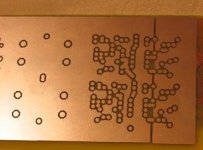
The ground plane is cut on the PCB, see attached picture, all the 0v sense parts are connected to the RHS copper. The components connected to power ground, in the schematic, are attached to the LHS copper.
The unused pins of the opamp are not connected to anything, that would be pins 1,5 and 8. Pin 4 solders to the LHS power ground copper.
How do you recommend I wire this up for testing? At the moment, I've made one small join between LHS and RHS copper, and connected V sense directly to the output.
AndrewT said:
Thanks Ill look into it.
Attachments
When you test you don't have to worry about the sensing function. Just short them on the pcb. You may also start without a preregulator AND taking the supply voltage for the opamp from the raw voltage. If it then works the basic circuit works. If you then move the supply voltage then you'll have startup phenominas and stability issues. Ideal conditions for the opamp is when the output voltage from the opamp is about half of the output voltage. It should be at least well within the opamp's limits which is 2 under supply voltage and 2 volts above ground.
Start to use a rather average opamp in speed. OPA134 is OK and the pass transistor could be BD139 if you don't have D44H11. A slow transistor like 2-4 MHz is not a good idea to use.
If you use AD825 you will have a perfect pcb otherwise you'll have oscillations. If you'll check ALW's boards you'll have an idea how it could look like. Check his starground concept. My pcb is smaller and uses a groundding concept similar to stargrounding.
AndrewT said:Hi Janneman,
the bottom ends of the measuring bridge are both terminated on the ground plane. Could this cause part of a sensing/oscillation problem?[snip]
Well, so far we have no clue what the problem is, don't we? Why going around in circles speculating (unless you enjoy wasting time as inefficiently as possible)?
Just measure, and get it fixed.
Jan Didden
- Status
- Not open for further replies.
- Home
- Amplifiers
- Power Supplies
- Jung/ALW reg issues.