Hello Günni,
I see that while unzipping the zipped gerbers, there are 2 folders. Folder 1 containing the gerbers and folder 2 containing the drill file. This may probably be the reason why jlcpcb site is not showing properly.
Just a guess. otherwise everything is properly formatted as xrk already got them manufactured.
If gerbers are ok with gerberlogix, they will be ok for manufacturing, my experience.
regards
Prasi
Last edited:
Amazing looking pcb, congrats Prasi.
Quick question; there are 6 output terminals (4 x Gnd, 1xV+, 1xV-)
Looks this this pcb is intended for mono amp.
I believe it would be better to have (2x Gnd, 2xV+, 2xV-) this way people can use a single cap mult to power a stereo amp.
My 2 cents
Eric
Quick question; there are 6 output terminals (4 x Gnd, 1xV+, 1xV-)
Looks this this pcb is intended for mono amp.
I believe it would be better to have (2x Gnd, 2xV+, 2xV-) this way people can use a single cap mult to power a stereo amp.
My 2 cents
Eric
Hello Eric,
Yes, you are correct. I missed out.
However there is following solution.
If one requires 2 numbers of V+ wires, a two pin terminal block can be made to fit for the V+ terminal if your C4 is 10mm dia. otherwise horizontal termi block would fit easily.
1712724 Phoenix Contact | Mouser India
regards
Prasi
Also, beware that when using a single cap mx to power two amp PCBs, you run the risk of pesky ground loops.
Hello Günni,
I see that while unzipping the zipped gerbers, there are 2 folders. Folder 1 containing the gerbers and folder 2 containing the drill file. This may probably be the reason why jlcpcb site is not showing properly.
Just a guess. otherwise everything is properly formatted as xrk already got them manufactured.
If gerbers are ok with gerberlogix, they will be ok for manufacturing, my experience.
regards
Prasi
I manually placed the drill file in the same directory before re-zipping it. Then used that to upload to JLCPCB. $2 for 10 is quite the deal if an "add-on" to another order that you already have and that takes care of shipping. Under 100mm square board Gerbers are great to have on hand as add-on orders.
What I’ve seen creating the most ground loops is when using 1 power transformer feeding 2 Cap M.
1 transformer feeding 1 cap M (stereo) is usually ok OR
2 transformers feeding 2 cap M (double mono) is also OK
BR
Eric
1 transformer feeding 1 cap M (stereo) is usually ok OR
2 transformers feeding 2 cap M (double mono) is also OK
BR
Eric
I manually placed the drill file in the same directory before re-zipping it. Then used that to upload to JLCPCB. $2 for 10 is quite the deal if an "add-on" to another order that you already have and that takes care of shipping. Under 100mm square board Gerbers are great to have on hand as add-on orders.
Hello X,
is it possible to upload your Gerbers, you have sent to JLCPCB? If i do the same, as you did, i get an error on JLCPCB, says missing board outline. In the zip file it is present.
BR
Günni
Not sure why you are having so many problems. I just went to post #512, downloaded the file there, and submitted to JLCPCB - and it accepted it no problem. The Gerber viewer shows the board correctly. I also uploaded it to Online Gerber Viewer and checked there and it works too.
So here is the link to the tested Gerber file: https://www.diyaudio.com/forums/att...plier-cap-mx-gtose-mjohnson_r1_2018-08-31-zip
You might try renaming the extension of the drill file from .txt to .drd and place in same directory - this is done in the attached file below and it works well in Gerber viewer.
Attachments
Last edited:
Hi X,
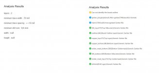
Thanks, but i have no problem with that. Attached you see, what the Gerber viewer from JLCPCB made out of your uploaded file😉.
See also the analysis results (2) and the automatic detection of size not works (3).
All other layers are ok.
BR
Günni
Thanks, but i have no problem with that. Attached you see, what the Gerber viewer from JLCPCB made out of your uploaded file😉.
See also the analysis results (2) and the automatic detection of size not works (3).
All other layers are ok.
BR
Günni
Attachments


I don't know what to tell you but just submit it because it worked obviously as I have boards from JLCPCB. I just downloaded the actual production file from their site and it is identical to the file Prasi posted on post #512. They will contact you and tell you if there is a problem.
A few hours ago I sent the Gerber from post 512 to PCBWAY, it passed their review without any questions.
The M2 has no on board rail caps if that's what you are asking. <snip>
Hi X, in my V-Fet built I guess I had the same issue. I removed 2 of the bridge rectifiers and fed both crc capbanks from one pair of bridges with the benefit of totally gone hum.
Cheer
Ernst
Nice! I will try that - so take a parallel output from two of the bridges (DC outputs) to a second cap Mx?
X, sequence is one big transformer, a pair of bridges, and then two CRC banks instead of one. So to speak parallel. One could do this smarter, as Nelson did in F7, but I just used two CRC boards in parallel. One for each channel.
The transformer has just two 18V windings and the pair of bridges is used as Nelson always uses them. One for the positive Voltage and the other for neg. Voltage.
Cheers, Ernst
Cheers, Ernst
Hi X,
Thanks, but i have no problem with that. Attached you see, what the Gerber viewer from JLCPCB made out of your uploaded file😉.
See also the analysis results (2) and the automatic detection of size not works (3).
All other layers are ok.
BR
Günni
It could be due to jlcpcb software for / rendering of gerbers may be faulty or there is a bug in the online viewer.
I would believe manufactured PCBs rather than some online viewer.
Like I said before, gerberlogix is quite mature and gives correct view of layers. My experience.
Regards
Prasi
The transformer has just two 18V windings and the pair of bridges is used as Nelson always uses them. One for the positive Voltage and the other for neg. Voltage.
Cheers, Ernst
Thanks for the tip, Ernst. It works!
I put a parallel set of DC outputs from each bridge to power two separate cap multipliers and the noise went away. I have 300uV rms on one channel and 100uV rms on the other with the source plugged into both RCA’s. The buzz is very faint and now hardly audible with ear at 12in away.
So a single dual secondary power trafo can indeed power two cap Nx in parallel. The amp PCBs still use a star ground with NTC’s though.
I am only using a pair of 10,000uF caps per cap Mx to smooth out the bridges. Compare that to my previous F6 PSU which required qnty 8 x 33,000uF caps. These Mark Johnson cap Mx are very cost effective as the major expense in the PSU was the capacitors before.
Last edited:
Perhaps try to relocate each channel's 'Star Ground' to the output GND point on each Cap Mx board and, if possible, use a separate NTC from each C-Mx output GND point to chassis earth.
This way you can get simplify the wiring and get rid of a lot of extra wires, and shorten the ones you keep = no ground loops at all.
Ifvyou haven't done it, you might look into replacing the GB bridges with Schottky ones - it makes quite a difference.
This way you can get simplify the wiring and get rid of a lot of extra wires, and shorten the ones you keep = no ground loops at all.
Ifvyou haven't done it, you might look into replacing the GB bridges with Schottky ones - it makes quite a difference.
- Home
- Amplifiers
- Power Supplies
- Juma's Easy-Peasy Capacitance Multiplier