Hello everybody.
I plan to share with you the construction of my new loudspeakers called 'Jubilo'.
Some time ago, I asked for some advices and opinions, which you can see here:
http://www.diyaudio.com/forums/multi-way/149062-advice-needed-build-new-3-way-active-system.html
Please forget the cabinet model presented there.
I started the construction of the loudspeakers back in January so in the first posts I will update the construction progress up to is current status. After that you might expect slow updates.
The drivers are:
Tweeter: Seas 27TBFC/G
Mid: 18Sound 6ND430
Woofer: Dayton RS270
The loudspeaker will be made of to separate cabinets. One with to woofers, and another on top in MTM configuration. The cabinets will be placed very closed together, so that the final format will be WWMTM.
Why two cabinets? well, first it will allow to place the mids and tweeters in a less smaller baffle, reducing baffle difraction. Second in the future I will be able to change the cabinets indenpendently of each others.
The crossovers remains the DCX2496. The amplifiers maybe A500 also from behringer. I still don't have one solution for the 6-ch volume controller 😡
First pictures 🙂
Since I wanted the cabinets to be curved, I needed to use a CNC that I was able to find neer the place I live. This pictures were taken in 2009-12-28.


In the last two pictures is possible to understand the final shape of the enclousure.
Since I wanted the cabinets to be curved, I needed to use a CNC that I was able to find neer the place I live. This pictures were taken in 2009-12-28.
In the last two pictures is possible to understand the final shape of the enclousure.
It tool a few days after to bought the adicional wood. I needed wood for the internal bracing, for the front baffles and back of the box, soo I used 19 mm MDF (3/4"). I also needed to create that curved side wall of the loudspeaker. Insted of cutting lots of pieces with the shape wanted with the CNC and stack all them on top of each other, i.e., several layers ($$$ being the reason not to do it), I used MDF with 3 mm (1/8") in the side walls, using 6 layers. Pictures will so better this technique.
First the pieces of the internal bracing (2010-01-17):


First the pieces of the internal bracing (2010-01-17):

The drivers are:
Tweeter: Seas 27TBFC/G
Mid: 18Sound 6ND430
Woofer: Dayton RS270
That mid seems like a mismatch to the others? Why did you choose it?
Yes, it seems. 🙂
My initial thought was to use the Dayton RS 150. But after some discussion here and in another forum, some fellows DIYers suggested the use of this drivers. Zaph tested those drivers and posted the result in his site. If you take a look, you will see how good they measure, especially in the THD departement. In terms of cost, I managed to buy those 6ND430 for 75€ each against 44€ of the RS 150. It was a hard decision for me. But after a while I thought that I should try it. Let's see wath I can come up with.
My initial thought was to use the Dayton RS 150. But after some discussion here and in another forum, some fellows DIYers suggested the use of this drivers. Zaph tested those drivers and posted the result in his site. If you take a look, you will see how good they measure, especially in the THD departement. In terms of cost, I managed to buy those 6ND430 for 75€ each against 44€ of the RS 150. It was a hard decision for me. But after a while I thought that I should try it. Let's see wath I can come up with.
Yes, I have know about about them, I do not have them but I have the 6ND410s. You do not have to convince me how much better then are over Daytons, I love them!
I guess I should have just posted, do you have a sensitivity mismatch?
I guess I should have just posted, do you have a sensitivity mismatch?
The 18 sound only appears to be an unusual choice simply because it isn't used more often. It doesn't really fit into the catagory of pro sound, it doesn't have the sensitivity for that, nor probably the power handling.
It is actually a reaonsably efficient mid/bass, which is rare these days. Where the designer has chosen to sacrifice some bass extension for a few more dBs sensitivty. It's a very attractive option, save for the square frame, in a world where 85-86dB are a dime a douzen.
As Zerevin is going active any sensitivity miss-match will be made academic and he can fully exploit the efficiency of the midrange driver.
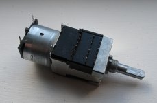
As to a 6 channel volume control Mouser stock a nice 6 channel pot at very little expense. I have one of these, although I am yet to use it, it does seem to be made to a decent enough standard.
Pot.
It is actually a reaonsably efficient mid/bass, which is rare these days. Where the designer has chosen to sacrifice some bass extension for a few more dBs sensitivty. It's a very attractive option, save for the square frame, in a world where 85-86dB are a dime a douzen.
As Zerevin is going active any sensitivity miss-match will be made academic and he can fully exploit the efficiency of the midrange driver.
As to a 6 channel volume control Mouser stock a nice 6 channel pot at very little expense. I have one of these, although I am yet to use it, it does seem to be made to a decent enough standard.
Pot.
Good to hear (read).You do not have to convince me how much better then are over Daytons, I love them!
The sensitivity mismatch will be handled in the DCX or amp atenuation, I need to reduce the output of the mids and the woofers to match the tweeter sensitivity.
Last edited:
Hi 5th element.
Finally I'm showing something here 🙂
Can you provide more information about those volume controlers? I didn't understood how they work 🙁
Finally I'm showing something here 🙂
Can you provide more information about those volume controlers? I didn't understood how they work 🙁
Hi 5th element.
Finally I'm showing something here 🙂
It's nice to be finally building something isn't it 🙂
Can you provide more information about those volume controlers? I didn't understood how they work 🙁
It's just a normal stereo, motor driven, potentiometer, except that it has three of them stacked together.
Attached is an image of the underside showing the three rows of pins, one row for each stereo section. The connection pinout is a standard one for this type of pot.
The pinout is detailed here.
Attachments


A month latter I finished the internal bracing of the top box, I had been busy with other stuff. 2010-04-14


Here you can see the side wall 1/8" MDF pieces (3mm). A lot of them 
48 pieces to be exact. 2010-04-17


48 pieces to be exact. 2010-04-17
2010-04-18 was a great day. It was the day that I had glued the first side wall piece to the internal structure. I was very anxious to see how it would work.
I had glued the first pieces with a friend of mine. It took one 1:15h to get the first piece glued.
But when I looked how it resulted, I was very pleased. After that we got more confident in our work and managed to glue the pieces faster.


I had glued the first pieces with a friend of mine. It took one 1:15h to get the first piece glued.
But when I looked how it resulted, I was very pleased. After that we got more confident in our work and managed to glue the pieces faster.


The construction technique looks very similar to what I am using at the moment to make a pair of stands.
I used google sketchup to draw the template shape, printed it out, stuck it to a piece of plywood then cut the wood to the shape of the print out.
Afterwards I used a template cutter on the router to make 8 of the same thing, then wrapped bendy MDF around the template, then filled it with mortar.
My description is horrendous so I'll just show a couple of pictures instead.
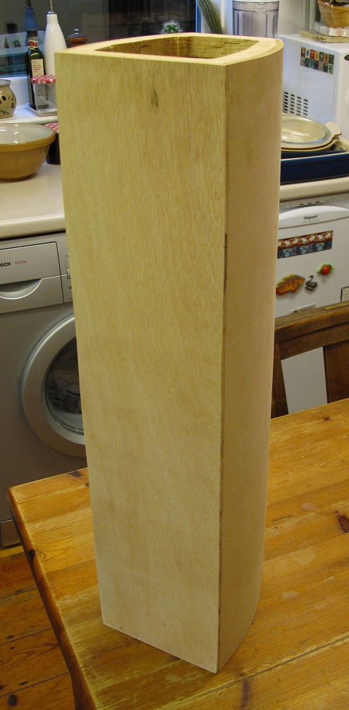
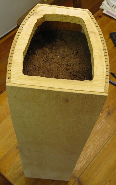
That's as far as I've currently got 🙂 One main column for one stand. I really wanted to check if the thin carcass could support the weight of all the mortar, which it could. It now weighs almost 19kgs.
I used google sketchup to draw the template shape, printed it out, stuck it to a piece of plywood then cut the wood to the shape of the print out.
Afterwards I used a template cutter on the router to make 8 of the same thing, then wrapped bendy MDF around the template, then filled it with mortar.
My description is horrendous so I'll just show a couple of pictures instead.
That's as far as I've currently got 🙂 One main column for one stand. I really wanted to check if the thin carcass could support the weight of all the mortar, which it could. It now weighs almost 19kgs.
Attachments


- Status
- Not open for further replies.
- Home
- Loudspeakers
- Multi-Way
- 'Jubilo' 3 way active loudspeakers, construction diary