Hi folks,
Just wondering if using JST connectors for connecting i2s signals from one board to another is a good idea?
Ive seen a few boards for sale that use the JST conector. Obviously some people see no problems with it.
Two-way Audio I2S two I2S in/out one out Switching Module - Audiophonics
What's the maximum length for i2s over a JST wiring loom?
Is JST better or worse than an IDE connector?
Why has the audiophonics board linked above got 10k resistors on the i2s inputs?
Last edited:
You should use GSGSGSGSGSG scheme for connecting I2S, and terminate it into 100-110ohm at source (series resistors). (G=Ground, S=Signal)
As for connectors themselves, none of these are great, but they do their work. I'd go with finer pitch. 2-row connectors might be better as you'll get more ground wires connected. Single ground wire is horrible idea 🙂
That board designer lacks any understanding of how digital signals work, that's the answer to all of the "why?"s 🙂
I2S is high speed single-ended logic signal with precise clocks, ideally 4 inches or less is good, its definitely not designed for going off-PCB and is not impedance-controlled. Upto 12 inches I'd certainly expect it to work but jitter on the clocks will likely be degraded. Converting I2S to multiple LVDS channels is one way to get more range, utilizing flat-flex interconnects(*). LVDS requires 4-layer boards and converters at each end, but being impedance-matched and properly terminated it will have much less jitter and skew, and is inherently more robust to EMI, as well as requiring less power when clocked at high rates.
(*) laptop LCD screens are driven using multiplexed LVDS signals over flat-flex with runs of 15 inches or more to ensure reliability (flat-flex is the only sort of cable that fits inside a laptop!)
(*) laptop LCD screens are driven using multiplexed LVDS signals over flat-flex with runs of 15 inches or more to ensure reliability (flat-flex is the only sort of cable that fits inside a laptop!)
Erin you will find information here i2s cable/wire type
the 10k resistors are for controlling impedance.Personally I use U.F.L cables.
the 10k resistors are for controlling impedance.Personally I use U.F.L cables.
Erin you will find information here i2s cable/wire type
the 10k resistors are for controlling impedance.Personally I use U.F.L cables.
On your advice I read all six pages.
But if I (or anyone else) was to try to use the board mentioned in the first post, or any of the spdif receiver boards available on eBay is there any recommended way to connect them to another board?
It seems most of the available boards for DIYers have JST connectors or some other pin strip output connectors.
So, the question is - sort of like the last unanswered question in the thread you linked- what's the best way to do it to maintain signal integrity (the bits arriving in the correct time without receiving or causing interference, or time skewing the data)?
Is it possible or impossible with these cheap boards?
I think you should do like s3tup to suggest,each signal cable with a ground on each side or wound on signal.
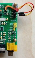
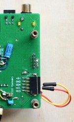
If you okay with dropping the connectors, then proceed with:
1. Solder a ribbon cable directly to the PCB pads
2. Scratch the PCB GND layer along the connector
3. Attach the copper foil tape to the cable, solder it into the PCB "pad" you've created in 2.
Something like this (on the right): http://s3t.it/data/uploads/dac_1541_v014_release02.png
It produces circa 90ohm line, so your resistors should be ~70R (taking into account some 10-20R output impedance of ICs).
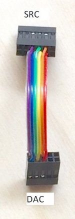
Alternatively, do the same with a ribbon, but connect every odd wire to gnd _directly_ to the PCB GND layer (don't follow Eldam's pic, its kinda better than single GND wire, but much worse than proper GSGSGSGSG connection).
1. Solder a ribbon cable directly to the PCB pads
2. Scratch the PCB GND layer along the connector
3. Attach the copper foil tape to the cable, solder it into the PCB "pad" you've created in 2.
Something like this (on the right): http://s3t.it/data/uploads/dac_1541_v014_release02.png
It produces circa 90ohm line, so your resistors should be ~70R (taking into account some 10-20R output impedance of ICs).
Alternatively, do the same with a ribbon, but connect every odd wire to gnd _directly_ to the PCB GND layer (don't follow Eldam's pic, its kinda better than single GND wire, but much worse than proper GSGSGSGSG connection).
If you okay with dropping the connectors, then proceed with:
1. Solder a ribbon cable directly to the PCB pads
2. Scratch the PCB GND layer along the connector
3. Attach the copper foil tape to the cable, solder it into the PCB "pad" you've created in 2.
Something like this (on the right): http://s3t.it/data/uploads/dac_1541_v014_release02.png
It produces circa 90ohm line, so your resistors should be ~70R (taking into account some 10-20R output impedance of ICs).
Alternatively, do the same with a ribbon, but connect every odd wire to gnd _directly_ to the PCB GND layer (don't follow Eldam's pic, its kinda better than single GND wire, but much worse than proper GSGSGSGSG connection).
Thank you very much.
I understand now.
- Home
- Source & Line
- Digital Line Level
- JST connectors for i2s