I went fishing inside my JD 1301 amp, originally in an attempt to locate the LM1875T feedback resistor. (I was hoping to make the feedback remote sensed)
While there, I caught a couple of 100 uF Aluminum-Electrolytics in the feedback network, to ground. I never liked the sound of this amp compared to my Jolida JD 102B, an all tube unit I have running JJ EL84s in triode mode. I figured out why.
I appreciate this forum where I read that it's basically OK to eliminate these caps. I did so and measure ~30mV on each channel's speaker outputs, which I also read wont be a problem.
Making this one change has rendered the little amplifier wonderful sounding, on par with the tube unit if not better. I assume the idea behind this amp is a tube stage providing some 2nd order harmonic distortion, followed by a power amplifier with zero distortion - at least at the levels I listen at.
This architecture works across a wide range of system implementations, from a little easy-peasy amp the JD 1301 is, to that which was reviewed in this Stereophile article Lamm Industries L2 Reference preamplifier | Stereophile.com
There, we have a $13,600 preamp with "an absolute dominance of the second-order harmonic", followed by a pair of Krell 350MC monoblocks. Not claiming the little Jolida has the same sound as $50K worth of hardware, only the same idea.
And once I got rid of those little 100uF Al-Els in-the-signal-chain buggers, it sounds a lot more in the right direction. Just in case anyone has this amp, or is using the "stock" LM1875T circuit, that cap makes a difference. It should be eliminated, or of the same quality as the best cap in the signal chain.
Yes, I should probably put fuses in the speaker wiring - and hope the coupling caps from the tube stages never leak. I realize the LM1875 part is coupled all the way to DC now, opening the door for such trouble.
If I knew that cap was there, I would have never bought the amp in the first place. They put polyprops coupling the tube outputs, then these little POS - with AC audio across them (worst case) no less, as it's a +/- power supply to the chip. Hope this helps someone. Thanks for the info being here and to the folks putting that here over the years.
Last edited:
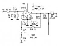
Today I modified the LM1875 feedback section to be similar to this;
The amp's stock feedback component values were 22k, 1k to a 100 uf cap to ground.
I replaced the 100uf with a 1k resistor. I connected a second 22k to this junction, then to the speaker side of a 0.27 ohm resistor I put in series with the amp's output (+).
The feedback arrangement apparently combines voltage feedback with current feedback, which I assume also increases the amp's output impedance. Replacing the upper 1K resistor with a potentiometer, I assume one could then make the output impedance vary from a voltage amp towards a current amp.
Maybe not all the way to infinity, but enough to more closely emulate (and perhaps go well beyond) 4-8-16 Ohm amplifier output impedances associated with transformers and tubes.
For now, I think I was able to substantially improve the sound of this little amp by simply adding in a few resistors I happened to have lying around in the right places. I really like this kind of mod.
The music definitely takes on a bit more life and I easily notice that recording quality is revealed - both ways; lousy and great - listening to jazz streams of songs I've never heard before. Head over the Radio Paradise flac streams, where I might catch an old classic from my generation, it's fun to realize I dont think I've ever heard "Funk 49" that clearly - it's easy to be hit like that.
I'll for sure be experimenting with bigger / better current sense resistors. Perhaps adding a Linkwitz damped output inductor would help to shield that speaker side feedback input from noise on the speaker cables.
Attachments
Hello,
I apologize for replying to an old post.
I have just noticed that my jd1301 sounds more alive than my expensive tube amplifier and I have decided to improve a bit on it. I have just ordered a stepped attenuator, better caps etc and came across your post about the removal of the negative feedback loop!!! I certeinly hope you will spare a few minutes to comment on your long term experience with that! I spoke with Steve Deckert of Decware and he mentioned that some SS amp designs with NO negative feedback would rival his tube amps (of which I have two).
Unfortunately...I gave up all my tube stuff and put that money into speakers. I got a pair of Lii F15s, and some Mark Audio drivers, which are "assisted" by 18" woofers on each side. In order to make that work, I needed some sort of multichannel DSP - and the Zoudio amplifier came along, which I've been using two units of, in two, two way systems.Hello,
I apologize for replying to an old post.
I have just noticed that my jd1301 sounds more alive than my expensive tube amplifier and I have decided to improve a bit on it. I have just ordered a stepped attenuator, better caps etc and came across your post about the removal of the negative feedback loop!!! I certeinly hope you will spare a few minutes to comment on your long term experience with that! I spoke with Steve Deckert of Decware and he mentioned that some SS amp designs with NO negative feedback would rival his tube amps (of which I have two).
So I lost the chance to give you the experience over the ensuing years. It was a neat little box; what I liked about it the most was that it used through hole components on the PCB, so I could actually work on it. Sometimes, even without having to disassemble the whole thing first. Imagine that.
I've since collected up a few "tube amplifiers", so my romance with them isnt completely dead; though it is possible I'd never get around to actually using them. If I were you, I'd stick with my Decware's and only fool with the JD for fun and to try to learn something. You're so happy when you hook up something like the above and it's stable after the power comes up!
Good morning, thank you for answering. I looked up the Lii f15, out of curiosity. I have 10 inch alnico audio nirvana fullrange speakers and they're fabulous! I manage to power them with 6 watts or even 2 watts per channel. All was well, but I built a 60 watt SS amplifier (van Alsteen) for my dad and it just sounded more ...like music, more dynamic, albeit flat as hell, devoid of the 3d magic. I told myself i could not trade the tube 3d soundstage for better bass control and dynamics, but now I hooked up the jolida 1301 to my speakers and it sounds 3d too, along with the rest of the SS benefits. My immediate reflex was to want to replace the stock volume pot, film caps in the signal path etc. Parts are ordered.
I hope i'll thus get rid of a certain unpleasant quality in the timbre, that makes it sound a bit shouty. That is why when I read your post I made a connection between that annoyance and the design employing negative feedback .
Would you perhaps guide me briefly through the removal of the negative feedback loop? I'm afraid I do not have enough information in your post above to feel secure enough to proceed 🙂 I'm not savvy enough either to assess the risk involved... To my speakers that is. Or perhaps you could point me to the forum where this is discussed?
Thank you very much.
these are your words: I replaced the 100uf with a 1k resistor. I connected a second 22k to this junction, then to the speaker side of a 0.27 ohm resistor I put in series with the amp's output (+).
Losing the capacitor makes it so it has other than 100% feedback at zero frequency, or DC. This circuit is common with the capacitor to ensure no DC offset at the output. As I recall - at least in my instance - the DC offset I saw after replacing the cap with the resistor was negligible. When you do this easily reversible change, you'll want to measure the DC offset before connecting to your speakers.I am above all wondering if you could find the time to look briefly into this, I understand that you have moved on to other adventures 🙂 Thank you Radu-Christian Barca
Also easily reversible is adding a 0.27 Ohm in series with the hot output lead. I just pulled the wire off the PCB, where I temporarily soldered that resistor, then connected the output wire to the other end. Adding a 22K to the center tap of the two 1Ks was a cinch.
It should add a little current feedback into the output amplifier. Try it and see if you hear anything positive. Another way would be to put the 0.27 to ground, connect the speaker ground wire to the other end and then, after removing the cap, connect the cap side of the 1K (R13) to this resistor-speaker ground wire junction.
Cant remember why I didnt do it this way, perhaps something intractable about how the speaker ground leads were done, vs the hot lead. That is, it would have taken a lot more work... Good luck and let us know how you think its sounds!
thank you very much for answering. I will try all of this as soon as i receive the parts. For now, i realize you are talking about a 0R27 resistor to +, not a 27R, am i right? What would be its power rating?
Imagine your 8/4 Ohm speaker going through 27 Ohms to get to ground. Of course it's 0.27. That's not a magic number either; I'd try other sub-Ohm values to suit what you hear.not a 27R, am i right? What would be its power rating?
Mine were 5W, but that's just because it was what I had on hand. It's not going to dissipate much; say 8 Ohms is dissipating 24W, so each Ohm is dissipating 3W and this additional resistor is ~1/4 of that. At normal listening levels, even less.
View attachment 1130122Hello and happy new year! I apologize for being insistant; I am obsessing over how good this Jolida 1301 sounds compared to my other amplifiers, which all cost a lot more. It is transparent, the bass is well controlled etc, now that I have upgraded a number of key parts. It just sounds best, regardless of price. The only gripe I have with it is a certain ...timbre, which seems independent of coupling cap brand etc, so I am about to try to modify the feedback loop. I was wondering if the schematic I am attaching to this post reflects your instructions. I am above all wondering if you could find the time to look briefly into this, I understand that you have moved on to other adventures 🙂 Thank you Radu-Christian Barca
Hi
Can you elaborate on the problem of timbre and l will listen for it in the LM 1875 l owned ?
Last edited:
Oh hi, I don't know how I could miss your post, I apologize. In the meanwhile I replaced all resistors directly in the signal path with naked z vishays, the 1uf coupling caps with mundorf silver gold and the volume pot with a stereo khozmo attenuator. I still find the midrange and highs somewhat annoying, compared to my all-tube amplifiers and I think soundstage consistency could be better, which I always felt with SS amplifiers. The annoying quality of the highs and midrange is hard to describe accurately, obviously. I have gotten used to it, but it is still very much there. I appreciate the ease with which it controls the bass and its amount, again compared to my anemic flea watters.
I received the new parts today from partsconnexion and I hope to operate on the feedback circuit tomorrow, then i will let you know how it went and how I think it sounds, if i get to that stage 🙂
I replaced all rectifying diodes with FR shottkys and the 100uf caps in the tube stage with large film clarity caps. I got rid of the .1uf cap in parallel with the last 100uf cap and I believe I should also lose the .01 caps straddling the rectifying diodes, would you agree?
I am powering the output stage with an entirely separate power supply unit that I had built for a pass lab F4= improvement in smoothness and tightening of bass + visibly better dynamics.
The Murado wood box is the Jolida. The ugly towels protect my REL subs from the cat. The Jolida has made them obsolete.

I guess if it was me I'd leave those in place. I've seen lots of applications with the caps across the diodes - how can that hurt? Caps across the large value electrolytics will only lower the the impedance of the power supply over frequency - unless you're trying to "tune" the power supply for best sound, where you want its impedance to change with frequency as a part of the amplifiers sound.I got rid of the .1uf cap in parallel with the last 100uf cap and I believe I should also lose the .01 caps straddling the rectifying diodes, would you agree?
I'm just not sophisticated enough to be able to say what power supply response best suits a chip amp, coaxing the best sound out of it for HiFi listening. I've seen typified an approach to throw a giga-farad across all rails and be done with it. The amp will work harder trying to track an input if its power supply rails are soft is the general thinking and that "work" maybe can be heard.
I left them in place 🙂
So I installed the resistors and measured DC offset. It was around 170mV while it lasted, then it went to zero and I believe the power supply to the otuput stage is out. I'll check the fuses.
They re both blown ;-( I wonder what went wrong
So I installed the resistors and measured DC offset. It was around 170mV while it lasted, then it went to zero and I believe the power supply to the otuput stage is out. I'll check the fuses.
They re both blown ;-( I wonder what went wrong
Last edited:
I may have shorted the output power supply. I replaced the fuses and rechecked the output board. Now it seems to function, I measure 27 and 35 mV DC offset on right and left channel respectively. Next step I'll hook up the lesser speakers and see what gives.
...music has been playing nicely for a while now. I am afraid to hook up my main speakers, simply because i do not understand what i have done to a degree where I could evaluate any risks to be. I don't know what could happen, what is the worst case scenario? What would go up in smoke, what in flames? i am going to need to calculate the values of the fuses I have to use on the two separate power supplies, i will need to read up on how one does that.
Which circuit did you use; resistor in the (+) lead or resistor to ground?I don't know what could happen, what is the worst case scenario?
I have been listening on my main loudspeakers for a few hours now. This mod had definitely impacted the tonality, and that was exactly what I was after. It has dissipated that quality that I associate with SS sound, that is somehow easily audible when distorted electric guitar is being played back. It sounded scratchy before the mod, now it sounds closer to the real thing. The first thing I noticed was a change in transiients, dynamic range seems to have increased, there seems to be a more aggressive attack on certain notes. I could not hear any improvement or change in soundstage depth though and I have a feeling that a certain segment of the low frequencies has become boomy. I like what it did to the highs and midrange. Next I will replace the 1uf mundorf caps with jupiter copper and see if I prefer the sound. My experience was always best with V-caps CuTf. Last time I used Jupiters they sounded muffled,in comparison but i am willing to give them a try since so many people like them. And besides, a pair of v-caps of that value will cost a fortune Thank you once again for the support and the inspiration.
And by the way i would love to explore this further if possible, with other resistor values...


And by the way i would love to explore this further if possible, with other resistor values...
Last edited:
- Home
- Amplifiers
- Chip Amps
- Jolida JD 1301 with LM1875T