No probs, Ken.
Still no advancement up the production list. I think we'll be well into July before the boards arrive.
On the upside, I have been working on a draft build manual. Just need to type it up...
Cheers
Jon
Still no advancement up the production list. I think we'll be well into July before the boards arrive.
On the upside, I have been working on a draft build manual. Just need to type it up...
Cheers
Jon
Is it possible to add my request for 4 boards?
Yes, it is. Welcome aboard and thanks for your supoort!! 😀
Please drop an email to jlh AT gt6 DOT co.uk as that is the master list. You'll get an auto-reply and I'll drop you a line when I've read your mail.
I've just seen that order number 1201 is in production!! 😎 Seeing as I have nearly finished drafting the build manual, this timing is good.
Cheers
Jon
Hi Jon
Any chance you could post the BOM so I can order parts ready for when the boards arrive. The link on the site doesn't work
+/- 18V needed.
Thanks for your hard work.
Rich
Any chance you could post the BOM so I can order parts ready for when the boards arrive. The link on the site doesn't work
+/- 18V needed.
Thanks for your hard work.
Rich
Hi Rich
Jon would most likely be in bed by now.
Using the JLH Ripple Eater with the Current Limiter bypassed, the voltage OUT is the same as the voltage IN.
You could use a typical dual voltage regulator ahead of it ,
such as the KC5418 from Jaycar, or similar. (LM317/LM337)
Headphone Amplifier Power Supply Kit - Jaycar Electronics
You would use it with a 18-0-18VAC transformer, and change the values of a couple of resistor values to get +-18V OUT,using the formulas given in the data sheets.
Alternatively you could find a way to fit a couple of 2K multi turn trimpots to adjust for +-18V, instead of using the original 1K1 resistors.
Alex
P.S.
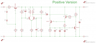
The attached schematic may give you some idea of what is required. The 2,200uF 10v low ESR capacitors per supply rail may be replaced by 2 x 4,700uF 10V low ESR capacitors per supply rail for a small further improvement.
You would need to check with Jon to see if they will physically fit his layout.
Uploaded with ImageShack.us
Jon would most likely be in bed by now.
Using the JLH Ripple Eater with the Current Limiter bypassed, the voltage OUT is the same as the voltage IN.
You could use a typical dual voltage regulator ahead of it ,
such as the KC5418 from Jaycar, or similar. (LM317/LM337)
Headphone Amplifier Power Supply Kit - Jaycar Electronics
You would use it with a 18-0-18VAC transformer, and change the values of a couple of resistor values to get +-18V OUT,using the formulas given in the data sheets.
Alternatively you could find a way to fit a couple of 2K multi turn trimpots to adjust for +-18V, instead of using the original 1K1 resistors.
Alex
P.S.
The attached schematic may give you some idea of what is required. The 2,200uF 10v low ESR capacitors per supply rail may be replaced by 2 x 4,700uF 10V low ESR capacitors per supply rail for a small further improvement.
You would need to check with Jon to see if they will physically fit his layout.
An externally hosted image should be here but it was not working when we last tested it.
Uploaded with ImageShack.us
Last edited:
Thank you Alex for the quick reply.
I would be using the JLH in a preamp power supply. Should I use smoothing caps and rectifier in front of two ripple eaters, one for each rail?
I would be using the JLH in a preamp power supply. Should I use smoothing caps and rectifier in front of two ripple eaters, one for each rail?
Hi Rich
Yes , you could, but in that case I would recommend the current limiter circuitry be fitted.For a preamp I would recommend a small dual regulated PSU using either the
LM317/LM337 or perhaps 7818/7918 after the rectifier diodes and filter caps.The 7818/7918 are however not so readily obtainable.
The JLH has a heavy initial in rush current which is best handled by the current limiting feature of the voltage regulators.
Alex
Last edited:
OK thank's Alex
I found some 7818 / 7918 on ebay.
I'll try the power supply you advised or even this one:
Universal +/-15V Power Supply - Jaycar Electronics
I could swap the regulators for the 78xx and increase the capacitance of the smoothing caps
I found some 7818 / 7918 on ebay.
I'll try the power supply you advised or even this one:
Universal +/-15V Power Supply - Jaycar Electronics
I could swap the regulators for the 78xx and increase the capacitance of the smoothing caps
BOM etc
Hi Rich,
You'll find the BOM, schema and a board image in post #71. Please feel free to have a check for any errors. We've already been through it once, but will do so again before publication. Thanks for stepping in with the info, Alex - yes I was in bed!! 🙂
I will be finishing the build manual by building a pair of production boards to the BOM therein. This will validate the BOM and provide some photos for inclusion. The Manual is aimed at newcomers, but will include, for more experienced builders, a summary at the start of the build section. Actually, all you need is the BOM and you'd be able to plop this project together in no time at all.
The board has been designed to accept the 4700uF 10V low ESR caps.
BTW, I do need to amend the schema to include the test points and sample voltages. The schema is good otherwise.
Cheers
Jon
Last edited:
Excellent Jon, Thanks
I did quickly skim through the thread to look for the BOM but obviously missed the post there.
Much appreciated.
I can help with the GT6 web page if you like. Have PM'd you.
Rich
I did quickly skim through the thread to look for the BOM but obviously missed the post there.
Much appreciated.
I can help with the GT6 web page if you like. Have PM'd you.
Rich
A few links that may be of help.
For the 2SA1930 and 2SC5171, the following companies/ebay people have been used.
eBay My World - audiowind-2005
Cricklewood Electronics - CCTV. CCTV Equipment. CCTV Systems. Digital CCTV Cameras
ELECTRONIC COMPONENTS, SEMICONDUCTORS, PARTS, TRANSISTORS, INVERTERS, TRANSFORMERS | DALBANI
They'll be plenty of others, but people who have built previous versions of this circuit have received genuine parts from the people above.
The C4 caps: Good results have been had using Suntan 2200uF or 4700uF low esr caps, available from Jaycar Electronics.
Also, some found that using a Panasonic FC for the 100uF cap on the output maintained the 'neutrality' of the sound (Dons flame suit, etc, etc)
It'll be interesting to get some feedback from you guys who are buying the board, once you have built it, as a lot of work has gone into this board.
The board hasn't been tested beyond around 650mA. But, as this version uses 2oz copper, it may take more. You would need to run without the Current Limiting section of the circuit, and should make sure that you have some sort of current limiting device in front (like a 317/337).
SandyK would be able to advise in more detail. I'm not the tech bod WRT this, just the salesman (and a bit of silkscreen tidying)!!! 😉
SandyK would be able to advise in more detail. I'm not the tech bod WRT this, just the salesman (and a bit of silkscreen tidying)!!! 😉
- Status
- Not open for further replies.
- Home
- Group Buys
- John Linsley Hood Ripple Eater