" R3 is optional. Fit for added performance only if Q1 and Q2 are matched. You can match hFE on your digital multimeter - do it, fit R3, know you've done a good job!"
I would recommend fitting this resistor irrespective. Most transistors from the same batch are often reasonably close in HFE and VBE.
Alex
Thanks Alex.
When I do a final validation on the BOM, I'll make sure that R3 is not optional!! 😀
Jon
An important point, folks:
The BOM above and the schematic at GT6.co.uk are for the single-sided version. Parts are the same, but I have renumbered the resistors in the new board. All boards will be shipped with a copy of the schematic (the same, with renumbered parts) and the current BOM (the same, with renumbered parts). If you want a look, the current board images are on GT6, and you'll see that most parts have been renumbered.
Cheers
Jon
I've been checking the latest schema and will update that ond the BOM later today. I can tell you that we are very near to placing this order!
Thanks for your support
Jon
Thanks for your support
Jon
I am 110% in agreement with Puffin. 😀 I like the fact that it is quite accommodating to various voltages and currents. I'm curious as to how a LM317/LM337 Ripple Eater combo compares to say one of the super reg circuits or shunt reg circuits out there. Maybe one of the many folks who will try this will chime in at a later date.
Rock Grotto 84
Liliya 2
audi0 4
sandbasser 4
Jaimo 4
EUVL 12
housing 4
sandyhooker 2
piero7 2
ymwong 8
jims 10
Ed LaFontaine 6
jrenkin 4
pchw 4
paudux 6
neutron7 4
ppcblaster 10
puffin 10
grufti 4
touchdown 6
thosuk 6
cliff 4
MoodySteeve 4
udailey 6 UPDATED
korben69 4
fredlock 4
fff0 4
TheShaman 3
johngalt47 4
awpagan 4
Ginum 6
johnYks 12
finneybear 4
jimt 4
TOTAL 259
I am 110% in agreement with Puffin. 😀 I like the fact that it is quite accommodating to various voltages and currents. I'm curious as to how a LM317/LM337 Ripple Eater combo compares to say one of the super reg circuits or shunt reg circuits out there. Maybe one of the many folks who will try this will chime in at a later date.
I've tried it. The LM317/337 Jaycar Headphone Amp PS and JLH measured at around 3mV ripple on my bog-standard multimeter. The TeddyReg I measured was pretty much rock steady. I use an ALW Super Reg to power my lightspeed clone. That is a reasonably complex and relatively expensive reg.
The ripple eater does a decent job and is good value for money. It isn't state of the art, but isn't meant to be.
I have today reviewed the schematic and re-written the BOM. Once it has been indpendently checked by my mate, I will post it here, on Rock Grotto and on the GT6 webspace.
I will be ordering 400 of these boards. This will be a one-off.
Once the boards arrive, I'll need to zone up some packets. What do people want? Airmail, of course, but do you want it Signed-For?
Cheers
Jon
Last edited:
The ripple eater does a decent job and is good value for money. It isn't state of the art, but isn't meant to be.
That's good enough for me!
Thanks for letting us know what we'll get out of this.🙂
Updated everything!!
Hi Everyone,
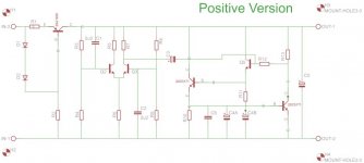
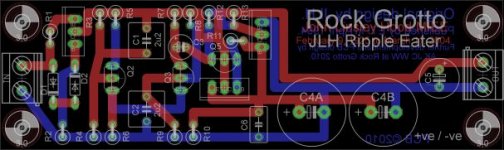
Here is the updated BOM and schematic - and a picture of the whole board.
I have updated GT6 . You will find larger versions of the schema and board here. EDIT: Having a bit of trouble with the images. Seem to be fine in FTP, but not linking correctly. The images here are the best bet for now. Sorry!
Please feel free to cross-check the BOM, schema and board. I have already done so, and a friend is hopefully going to cast his eyes over it as well. Please let me know of any errors you may find (I think there are none!!), before I place the order for these boards next week.
Cheers
Jon
Hi Everyone,
Here is the updated BOM and schematic - and a picture of the whole board.
I have updated GT6 . You will find larger versions of the schema and board here. EDIT: Having a bit of trouble with the images. Seem to be fine in FTP, but not linking correctly. The images here are the best bet for now. Sorry!
Please feel free to cross-check the BOM, schema and board. I have already done so, and a friend is hopefully going to cast his eyes over it as well. Please let me know of any errors you may find (I think there are none!!), before I place the order for these boards next week.
Cheers
Jon
Attachments
Last edited:
Rock Grotto 84
Liliya 2
audi0 4
sandbasser 4
Jaimo 4
EUVL 12
housing 4
sandyhooker 2
piero7 2
ymwong 8
jims 10
Ed LaFontaine 6
jrenkin 4
pchw 4
paudux 6
neutron7 4
ppcblaster 10
puffin 10
grufti 4
touchdown 6
thosuk 6
cliff 4
MoodySteeve 4
udailey 6 UPDATED
korben69 4
fredlock 4
fff0 4
TheShaman 3
johngalt47 4
awpagan 4
Ginum 6
johnYks 12
finneybear 4
jimt 4
Westley 12
m461c14n 4
Total: 275
I'm going to order 400 boards once the layout is validated. There will be enough for everyone. I'll post ordering details when I have the boards in my sticky mitts. No payments wanted until I let you know exactly what's what.
Thanks all.
Jon
Thanks all.
Jon
Hello Jon,
Can we make the PCB smaller by removing the wordings on the PCB top right hand corner? Then insert the wordings some where else like in between the tracks or so?
Can we make the PCB smaller by removing the wordings on the PCB top right hand corner? Then insert the wordings some where else like in between the tracks or so?
Of course fff0 is correct. But there is something kick a## about a pcb with Rock Grotto Ripple Eater on it.
I don't think it's worth your while to change it at this point. Only if there's an error somewhere.Hello Jon,
Can we make the PCB smaller by removing the wordings on the PCB top right hand corner? Then insert the wordings some where else like in between the tracks or so?
Hello Jon,
Can we make the PCB smaller by removing the wordings on the PCB top right hand corner? Then insert the wordings some where else like in between the tracks or so?
Hi there,
Sorry, board design is now frozen. This design has been test-etched and has been electrically proven. To give some background, not only are we using the copper layer to place provenance information, but the large 4700uF caps (C4a, C4b) may be mounted lying down to reduce stacking height. If you opt for this method, then the FR4 real-estate in that location is required.
Method in the madness! 😀
Cheers
Jon
BTW, I'm more than happy to share the EAGLE .sch file with you if you'd like to experiment with alternative layouts.
Hi there,
Sorry, board design is now frozen. ........ but the large 4700uF caps (C4a, C4b) may be mounted lying down to reduce stacking height. If you opt for this method, then the FR4 real-estate in that location is required.
..........No problem mate.
Its a good idea given by you for lowering the stacking height.
I am interested, but before ordering would like to know if this could be used in power amps psu's? I think AndrewT suggested it could be configured for 5A? Could it be good even for 10A? Could someone direct to a link to show me an implementation in a power amp?
(Edit) an unregulated psu...
(Edit) an unregulated psu...
Last edited:
- Status
- Not open for further replies.
- Home
- Group Buys
- John Linsley Hood Ripple Eater