Also. It allows zero CM distortion from the amp input, but still independent setting of the termination impedance Rt and the feedback gain resistors. Have your cake and eat it, too 😉
Not my circuit, unfortunately.
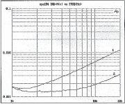
Curve 1 is 'classic' circuit with inverting amp and the input to +terminal and ground.
Curve 2 is the new one.
Actually, with Scotts' AD797 the difference is much smaller, ands only above 10k or so. Why is it that we always end up with his sandbox 😉 ??
Jan Didden
Not my circuit, unfortunately.
Curve 1 is 'classic' circuit with inverting amp and the input to +terminal and ground.
Curve 2 is the new one.
Actually, with Scotts' AD797 the difference is much smaller, ands only above 10k or so. Why is it that we always end up with his sandbox 😉 ??
Jan Didden
Attachments

Hi Jan,
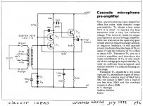
This is the scheme of a "series feedback connection with reduced common mode distorsion" as Eric F. Taylor described it in his famous article "Distorsion in low-noise amplifiers", Wireless World, august and september 1977. He used it for a RIAA preamp.
Some monthes later, a mike preamp with the same NFB connection was published as a circuit idea in the same magazine:
Attachments
forr said:Hi Jan,
This is the scheme of a "series feedback connection with reduced common mode distorsion" as Eric F. Taylor described it in his famous article "Distorsion in low-noise amplifiers", Wireless World, august and september 1977. He used it for a RIAA preamp.
Some monthes later, a mike preamp with the same NFB connection was published as a circuit idea in the same magazine:
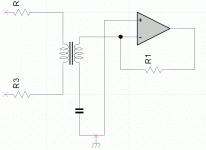
Yes it looks conceptually the same! The circuit I posted is described by Kovinic, Drincic and Jankovic from Belgrade and Sussex, in AES paper 7760.
Jan Didden
End of page
http://www.aes.org/events/126/papers/session.cfm?code=P20
P20-6 Low Noise Transformer Input Preamp Design—A Solution that Eliminates CMID—Milan Kovinic, MMK Instruments - Belgrade, Serbia; Dragan Drincic, Advanced School for Electrical & Computer Engineering - Belgrade, Serbia; Sasha Jankovic, OXYGEN-Digital, Parkgate Studio - Sussex, UK
This paper examines more closely the advantages of input transformer-op amplifier configurations, especially those implemented in low-noise designs. Usual transformer input stage topology works in non-inverting architecture, since it allows the transformer to work with optimum loading, to maximize the signal-to-noise ratio. However, this configuration is subject to Common-Mode voltage Induced Distortion—CMID. The susceptibility is further increased if the amplifier source impedance is not perfectly matched. This is illustrated by tests on popular audio op amps. Advanced transformer input stage topology proposed in this paper completely prevents this kind of distortion. Noise performance remains unaffected, yet listening tests in practical application confirm the sound to be more pleasant.
Convention Paper 7760
janneman said:BTWW, what do you guys see as benefits, if any, of this?
One more. Very cheap transformer. No stinkin' diffamp with it's specific distortions.
Edit: used as a line input, with modem transformer.
Attachments
Edmond Stuart said:Nice. But what about the noise from R1 and R?
Line level input stage. 300 Ohm resistors, for 600 Ohm input.
If you are OK with feedback this is a very interesting option for a transformer input: Lundahl Zero Field Not usable for a mike input since it needs some drive from the source device.
1audio said:If you are OK with feedback this is a very interesting option for a transformer input: Lundahl Zero Field Not usable for a mike input since it needs some drive from the source device.
Even better than mine: they used a positive feedback...
noise
So?
Wavebourn said:Line level input stage. 300 Ohm resistors, for 600 Ohm input.
So?
Re: noise
Power loss in resistors, like in any attenuator. But look, how cheap is the transformer! 🙂
Think of it as an inverting opamp stage where between input resistor and an inverting input was squeezed a tiny transformer. It transforms so low level of voltages so does not show saturation on very low frequencies.
The majority of modern consoles have the same input stages for levels from thin microphone to huge line levels. They use attenuators on inputs. The same loss, the same noises. I can't use it for microphone input: too noisy, but for line levels it is quiet like a grave.
Edmond Stuart said:
Power loss in resistors, like in any attenuator. But look, how cheap is the transformer! 🙂
Think of it as an inverting opamp stage where between input resistor and an inverting input was squeezed a tiny transformer. It transforms so low level of voltages so does not show saturation on very low frequencies.
The majority of modern consoles have the same input stages for levels from thin microphone to huge line levels. They use attenuators on inputs. The same loss, the same noises. I can't use it for microphone input: too noisy, but for line levels it is quiet like a grave.
1audio said:
Per your request here is the schematic for the HP 15119C preamp. Its actually very simple. Input impedance is 1GOhm in parallel with less than 2 pF. The FET is an SFE793 (whatever that is, HP used it in a few products).
I'll dig out the B&K 2619 and post similar if I can find it.
Classic bootstrapped everything with driven shield. The noise noise of 500M (1G||1G) still appears at the input.
BTW the HP cross reference lists Motorola as the mfg. on that FET, I'll bet it's nothing special.

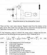
Yes that's true, that's the major low frequency noise component, it goes down as sqrt of R but rises at the low end at 20dB/decade so in general it overtakes 1/f noise. Simple RC stuff easy to compute, it gets tough when the capsule is only 5-10pF that's why MEMS mics use MOSFET's and diode reverse resistance for bias.
stinius said:Hi Wavebourn
Thanks for the email, answer sent, with a copy to our common friend.
I did not get any.
Can you, or our common friend, resend it on my e-mail address?
Thanks!
it gets tough when the capsule is only 5-10pF that's why MEMS mics use MOSFET's and diode reverse resistance for bias.
Does it mean Scott, that MOSFET has lower gate leakage current than JFET? But what about transconductance and 1/f noise in MOSFET? Thanks.
ok, I found reference: A. C. Pluygers A novel microphone preamplifier for use in hearing aids Analog Integrated Circuits and Signal Processing Volume 3, Number 2 / March, 1993
another reference: USPat 7110560
From 1968-1973, the B&K 2619 used two 200 meg input resistors in parallel for an equivalent of 100 meg. This is what I requested changed to two 2 gig resistors in parallel for an equivalent of 1gig ohm. We paid extra for this change, but they upgraded all the mike preamps later.
For the Grateful Dead mikes, we had already changed them, ourselves, but they were Nagra based instrumentation mike modules, not B&K 2619 preamps, and they were easier to modify.
For the Grateful Dead mikes, we had already changed them, ourselves, but they were Nagra based instrumentation mike modules, not B&K 2619 preamps, and they were easier to modify.
dimitri said:
Does it mean Scott, that MOSFET has lower gate leakage current than JFET? But what about transconductance and 1/f noise in MOSFET? Thanks.
Very large area MOSFET's in sub-threshold would surprise you on their gm/noise performance. There is some literature around on it.
- Status
- Not open for further replies.
- Home
- Amplifiers
- Solid State
- John Curl's Blowtorch preamplifier