Nelson Pass said:I believe the words to describe the distortion you want is
"monotonic character"
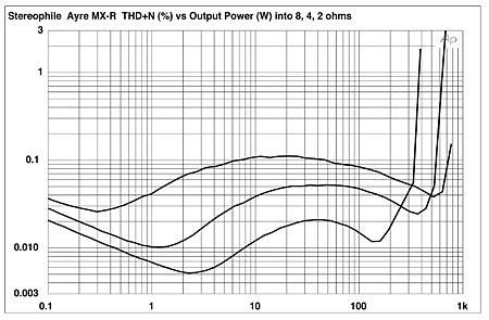
You mean like this?

john curl said:Bob, I use optimum Re value resistors and VOLTAGE DRIVE to the output bipolar transistors, per Barney Oliver. Where is the source then, of Gm doubling? And where do you think that I put the majority of my effort in an amp design?
Hi John,
As you have pointed out, Barney Oliver described the optimal bias situation for a class-AB output stage as occurring when the intrinsic (dynamic) emitter resistance of an ideal BJT at quiescent bias equals the value of the emitter resistor RE. This in turn occurs when the voltage dropped across RE is 26 mV. This is intuitively understandable by looking at the output impedance of the stage when voltage-driven and recognizing that we wish the variation of the net output resistance of the stage to be minimal as a function of output current in order to achieve minimal static crossover distortion.
When Oliver’s condition is met, the output impedance at one extreme of output current is asymptotically equal to RE as the BJT current goes high and its intrinsic emitter resistance goes very small compared to RE. Also, when his condition is met, the output impedance at idle of each half of the output stage is re’ + RE = 2RE, so the parallel combination is once again RE. Thus, the output impedance at idle is the same as that at extremes. Making these the same is about the best one can do to minimize crossover variation in net output impedance of the stage. All of this is valid for ideal BJTs.
If one strongly over-biases the output stage, well beyond Oliver’s criteria, the intrinsic emitter resistance of the BJT’s is very low, even at idle. Under these conditions, net output impedance of the stage at idle is closer to RE/2, and thus the gm of the stage has doubled in the limiting case of very high bias. However, the output impedance at extremes of output current, when only one output transistor is on, is still equal to RE. Thus, gm has doubled in the crossover region with respect to gm outside the crossover region. This gives rise to the term “gm doubling” (was it coined by Self?).
In the JC-1, the emitter resistors are 0.15 ohms, so a 150 mA bias per pair results in a drop of about 22.5 mV across each RE. This is pretty close, especially when we recognize that the effect of RB of the real-world BJT will tend to reduce the optimal value of RE. Indeed, RB divided by beta acts as an ohmic emitter resistance that is an extension of RE (but it lies inside the power transistor). The 2SC3264 has an RB of about 4 ohms and a typical beta of 75. This results in an ohmic contribution, as seen at the emitter, of about 0.05 ohms. If we recognize it as an extension of RE, then effective RE is about 0.2 ohms and a 150 mA bias current puts about 30 mV across effective RE. Still not bad.
However, the JC-1 also has 10-ohm base stopper resistors. These add to RB and create a larger effective ohmic resistance as seen looking into the emitter. This resistance will now be on the order of 14/75 = 0.19 ohms. Effective RE now becomes 0.15 + 0.19 = 0.34 ohms. We now have about 51 mV across effective RE, an over-biased condition with respect to the Oliver criteria. GM doubling will begin to appear.
Thus, it would appear that at a bias of 150 mA per pair, the JC-1 is experiencing gm doubling.
There are some mitigating factors that exist in the JC-1, however. First and foremost, the large number of paralleled output pairs greatly reduces the output impedance to begin with, so any variation due to gm doubling will be fairly small, anyway. Secondly, there may be some help from reduction of base resistance at higher currents that is typical in power transistors. This dynamic reduction in RB will tend to offset some of the gm doubling effect. There might not be much of this effect at Ic = 300 mA when the stage exits the class AB crossover region, however.
I’m not sure which of your bias levels you are referring to when you are discussing whether gm doubling is occurring or not. I assume that your intention was that low-bias meets the Oliver criteria and that high-bias is over-biased with respect to the Oliver criteria. Is that correct?
Finally, at high frequencies where it counts, I suspect that most amplifiers are driving their output stages in voltage mode. This will always be the case when the output impedance of the VAS is significantly lower than the impedance seen looking into the output stage. This will certainly be the case with a Triple output stage and a VAS whose output impedance is quite low due to the shunt feedback of Miller compensation.
Cheers,
Bob
I will say this about class B design. IF I could make the same quality product (as borne out by independent listener evaluation) with a class B design, as I can with a Class AB1 design I would use it exclusively. It is only a SWITCH POSITION that turns a JC-1 from a Class AB1 design to a Class AB2 design (like my critics use). It is there to try by anyone. Actually, I think that a multi amp design would be optimum, with CLASS D used for the woofer and even lower midrange. For the tweeter amp, I would still stick with CLASS A, just to keep the listener fatigue to a minimum. Start up new projects, fellow engineers, throw away your electrostatic speakers, tubes, etc. Use horns! Then you would be able to listen to your audio on a solar powered array.
Work on CLASS D! Get it better and better! There is no shame in this. Hobnob with Bruno, and learn everything that he has to share. (And people wonder why I use Prozac) 🙄
Work on CLASS D! Get it better and better! There is no shame in this. Hobnob with Bruno, and learn everything that he has to share. (And people wonder why I use Prozac) 🙄
anatech said:Hi Syn08,
That and the entire "lead thing" on top of that.
Lead free electronic products seem to be very unreliable in the long term.
Hey, you Canadian guys seem to have a very low regard for EU Standards.
They often get a bad press here in Europe too, but a lot of that is due to ignorance of what is in the standards and the purpose behind them.
As an example, my 42" Toshiba TV has less than 2W consumption in standby so it can't be that difficult to achieve, and remember that there has to be interpretation and definition of "standby" for different apparatus, so e.g. a network printer in a commercial setting will almost guaranteed NOT have to comply with the same requirement as a domestic amplifier, TV, CD player etc.
I will bet that not many of the "hi-end" amps being discussed here will even have a standy mode - just think of the effect that would have on the sound 😀 Doesn't bear thinking about putting some kind of remote control power in line with your (rip off) £200 power cord 😉
Standby doesn't mean the time you are changing CD and it isn't busy, it means when you have "put it to sleep" by remote control.
Bob, M-I-C, K-E-Y .... Give it a break, I am within guidelines, nothing is perfect, but why don't you MEASURE the crossover point, rather putting up a 'Chicken Little' objection to it?
The AYRE output distortion graph is NOT signal averaged. There is essentially NO measurable distortion below 2W in this design with this test equipment.
Hi Alan,
I don't care where the standard comes from. It should address the root of whatever problem it was created for. It is no surprise that military and life support are two classes that are exempt from the silly lead thing. They are excluded because solder with lead free systems is less reliable than the "good old" leaded solder systems.
I turn my sound equipment completely off when not in use. However, my new Cyrus (English) equipment goes into standby, not off. Hmmm. Low tech does have it's advantages sometimes. 😀
Hi John,
I'm not attacking you, and I'm not against you.
My comments were designed to be helpful to you. Read what I said again please. Your message is clouded by other things you say. Your technical message is fine.
-Chris
Not true in my case.Hey, you Canadian guys seem to have a very low regard for EU Standards.
I don't care where the standard comes from. It should address the root of whatever problem it was created for. It is no surprise that military and life support are two classes that are exempt from the silly lead thing. They are excluded because solder with lead free systems is less reliable than the "good old" leaded solder systems.
I turn my sound equipment completely off when not in use. However, my new Cyrus (English) equipment goes into standby, not off. Hmmm. Low tech does have it's advantages sometimes. 😀
Hi John,
I'm not attacking you, and I'm not against you.
My comments were designed to be helpful to you. Read what I said again please. Your message is clouded by other things you say. Your technical message is fine.
-Chris
john curl said:The AYRE output distortion graph is NOT signal averaged. There is essentially NO measurable distortion below 2W in this design with this test equipment.
I'm not talking about below 2W - that is an obvious issue with the "N" in "THD+N".
By anatech -The real issue would be the ability of consumer products to remain in service, and the serviceability of these products
With the new "solid" electrolytics ,(conductive polymer)
An externally hosted image should be here but it was not working when we last tested it.
I think they hope to offset the expected unreliability associated
with the new mandates.. The future (at least near term),
is for disposable , modular equiptment and repairs.
On the bright side , The DIY community has better
technology to make our projects with..😀
OS
andy_c said:
You mean like this?
It is quite easy to explain. First portion is burried in noise. Then, we can see middle-bias AB output stage (I would say about 500mA and low or no global feedback). Distortion starts to rise (in absolute level), then decreases, and then rises again.
john curl said:The AYRE output distortion graph is NOT signal averaged. There is essentially NO measurable distortion below 2W in this design with this test equipment.
No. There is a high-order distortion. I am not impressed, as I am not impressed by any other Ayre power amp.


PMA said:It is quite easy to explain. First portion is burried in noise. Then, we can see middle-bias AB output stage (I would say about 500mA and low or no global feedback). Distortion starts to rise (in absolute level), then decreases, and then rises again.
Exactly.
I think he said he was using 6+6 output devices, so they may meet the Oliver condition as well.
Nelson Pass said:
The B&O lobby, perhaps.
Can you quote the language of of the proposal?
😎
Something about "living in harmony". Actually it was power limits on Telco devices not home electronics per-se. But we recently had an Asian major player say that they would never adopt induction charging of phones because they are looking toward 95-99% efficiency.
john curl said:You have trouble with 'them' too, Nelson? What a bunch of ????.
No, I have a staff who solves those problems so that I can remain
un-medicated.
😎
Pleased to hear itanatech said:Hi Alan, Not true in my case.
It is no surprise that military and life support are two classes that are exempt from the silly lead thing.
The "silly lead thing" is part of what I was talking about. Over here it is not seen as that silly. Until recently one of my roles was as Quality Manager for a military computer manufacturer. We set up production for lead free and after training were perfectly OK with it. Due to the new soldering training everyone was put through, we actually saw a REDUCTION in failure rates and less returns from the field. OK we only had two years experience in it so didn't have long term failure data, but the initial results were good.
And because some of our equipment was considered dual use, it was not exempt anyway. In order to prevent cross contamination it was much simpler to have one standard, keeping service dept "isolated" to avoid old kit contaminating lead free workstations.They are excluded because solder with lead free systems is less reliable than the "good old" leaded solder systems.
Buy a good soldering station, learn to get a good lead free joint and reliability should be as good. You probably need to change the tip more often however 🙄
Out of interest, do you know how much power it consumes in that state ?However, my new Cyrus (English) equipment goes into standby, not off.
Hi ostripper,
-Chris
Having done warranty service for many, many years, I find no comfort in that at all. The disposable term bothers me greatly as it allows materials to hit the dump when it could be repaired. Modular is cool. That was a commonly advertised goal with the intent that you could upgrade performance when improved modules came out. I am in favor of that idea. ULC (Actually Underwriters and CSA) might go broke though, so forget that from ever becoming a reality. We need to return to the idea of durable goods. If equipment was properly aligned at the factory, that would help too.The future (at least near term), is for disposable , modular equiptment and repairs.
Yes, if we can adapt to new technologies. Still surface mount parts can not be reused whereas through hole parts can. Many DIYers harvest their parts from the cast offs. I surely did as a youngster when capacitors where beyond my financial grasp.On the bright side , The DIY community has better technology to make our projects with..
-Chris
alansawyer said:Buy a good soldering station, learn to get a good lead free joint and reliability should be as good. You probably need to change the tip more often however
That's the ticket. Try working with the regulations before whining too
much. We converted to lead-free solder, and it works fine, although
you're right about burning through tips.
😎
Hi Alan,
The act of training may have more to do with your quality increase than the soldering. Wait until everyone becomes comfortable with lead free soldering and see if the bad connection rates go up. I'm not saying they will, I'm just waiting for human nature to come into things again.
-Chris
Edit:
Hi Nelson,
I had been reading industry reports and made a judgment on those. EDN for one, and several others.
If anyone has positive experience with lead free solder, can I start a thread and have you post in there? Or, you could start a thread. Whatever you want. There are many of us who just don't know what works.
Edit (again):
Hi dimitri,
Thank you. That was my point, but I'm willing to keep an open mind.
I had to train new technicians how to solder. So in North America, there is no training at all for the techniques you need to know to perform your work. I understand our military does train, and one professor at Ryerson (in Toronto, Ontario, Canada) did train as well. Beyond that, anything goes. I learned how to solder from building Heathkit equipment, and being judged by older technicians. I was lucky.Due to the new soldering training everyone was put through, we actually saw a REDUCTION in failure rates and less returns from the field.
The act of training may have more to do with your quality increase than the soldering. Wait until everyone becomes comfortable with lead free soldering and see if the bad connection rates go up. I'm not saying they will, I'm just waiting for human nature to come into things again.
I have, and a hot air station. There are too many different lead free solder types. The last company that promised small samples didn't send them. If there was one accepted type, we could buy it and learn. Perhaps after industry shakes out the losers, we'll know.Buy a good soldering station
Good question. I haven't bothered to measure them yet. I do have to get rid of those BFA connectors, so I'll be working on them in the future. They are Mono X amplifiers, so you could look up the specification. They sound really very good. The first commercial product I have looked forward to hearing for many years.Out of interest, do you know how much power it consumes in that state ?
-Chris
Edit:
Hi Nelson,
I had been reading industry reports and made a judgment on those. EDN for one, and several others.
If anyone has positive experience with lead free solder, can I start a thread and have you post in there? Or, you could start a thread. Whatever you want. There are many of us who just don't know what works.
Edit (again):
Hi dimitri,
Thank you. That was my point, but I'm willing to keep an open mind.
sorry for OT
http://www.emasiamag.com/article-2706-rollbacktheleadfreeinitiative12rohsmyths-Asia.html
Roll Back the Lead-Free Initiative: 12 RoHS Myths
Howard Johnson, PhD, EDN
(1) Lead-free assembly is not better for the environment, it is worse. The additional tin mining required to produce high-purity tin alloys, plus the mining of other precious metals required to alloy with tin in substitution for lead is a poor trade for the use of existing lead, much of which comes from recycled products. This information comes from a study conducted by the U.S. Environmental Protection Agency (EPA). The study undercuts the primary basis for ROHS.
(2) Lead-free assembly is less reliable than lead-based assembly. The E.U. environmental commission admits this point. That's why they grant exceptions for military and high-reliability applications that still use SnPb solder.
- Status
- Not open for further replies.
- Home
- Amplifiers
- Solid State
- John Curl's Blowtorch preamplifier