john curl said:No, it is just that the hear-no-difference group have nothing to contribute on the subject and dilute the topic with vague insults.
I really feel sorry for those who feel insulted by vague insults.


Attachments

Let’s get back on the volume control.
How many steps are needed?
And how would you use the steps from 0dB to minus ? dB?
Stinius
How many steps are needed?
And how would you use the steps from 0dB to minus ? dB?
Stinius
stinius said:Let’s get back on the volume control.
How many steps are needed?
And how would you use the steps from 0dB to minus ? dB?
Stinius
At the risk of doing even more damage to the signal you could use two stepped attenuators. The first one sets a range and the second can make very small adjustments within that range.
This doesn't answer your question of how many steps are needed, but it does increase the number available by the multiple of the number of steps on the two.
If you listen mostly within one range you have a great deal of adjustment. If you change ranges you will get a large change in volume. You would want to set your ranges to a level that could be tolerated in one step.
No mention of TVCs?
High input impedance. Low output impedance. Doesn't change the signal to heat. Breaks ground loops. Blocks DC. Can feed it balanced or unbalanced.
High input impedance. Low output impedance. Doesn't change the signal to heat. Breaks ground loops. Blocks DC. Can feed it balanced or unbalanced.
Steve Dunlap said:
At the risk of doing even more damage to the signal you could use two stepped attenuators. The first one sets a range and the second can make very small adjustments within that range.
This doesn't answer your question of how many steps are needed, but it does increase the number available by the multiple of the number of steps on the two.
If you listen mostly within one range you have a great deal of adjustment. If you change ranges you will get a large change in volume. You would want to set your ranges to a level that could be tolerated in one step.
Hi Steve
It’s a good idea, and I see your point, but let’s set the limit to one stepped attenuator.
Stinius
Now we get to the issue of continuous range like pots and the steps of switch based attenuators. In most playback situations, steps can be just fine, but in the recording environment, sometimes you just have to fade smoothly.... Some of the digi-pots like the Cirrus parts mentioned above offer small enough steps to make a smooth fade, and could be used in that kind of application.
In most re-mastering studios, you see step switches on everything, even EQs, so that settings can be noted and returned to, and also they usually make better sound than the same gear fitted with pots. In the recording world, a lot of gear can be purchased in 'normal' form with pots, or in 'mastering' form with rotary switches on every adjustable function, usually at MUCH higher price...Given everything else is the same inside, the switched versions are always better sounding to my ear. Of course, in steady state signal testing, both versions will measure about the same....another topic altogether
In the recording studio, most consoles and outboard gear use NOTHING but pots and straight line "faders". In the straight line world, Penny and Giles has the market, all the best consoles use P&G, as had John Curl, in some of his past consumer and custom pro designs..They are slightly veiling or softening in nature, and as quiet as can be for a resistor.
The report on the Cirrus chip is at least encouraging...I might have to sample some up and give them a try just to see how they do....
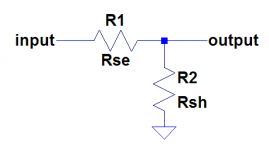
Here's a thought I had a while back for a "pot emulator" consisting of resistors and relays. The basic structure would be that of a series arm Rse and a shunt arm Rsh as shown in the picture below. Each of Rse and Rsh would consist of a bunch of series resistors with a relay across each one that is either open or shorts out its corresponding resistor.
Rse would look like this:
Rse = R + 2R + 4R + ... + 2(N - 1)R
Rsh would be the same as well, namely:
Rsh = R + 2R + 4R + ... + 2(N - 1)R
Suppose there were a digital word Xse controlling Rse such that the LSB of Xse opens or shorts R, the next bit opens or shorts 2R, and so on. There could be a second digital word Xsh that does the same for the individual resistor elements of Rsh.
Now, if Xsh were made to be the bitwise NOT of Xse, the input resistance would be constant, independent of the attenuation. So it would emulate a pot in that respect. The signal would go through a lot of relay contacts with this arrangement though. Has anybody else thought of this or tried it out?
Attachments

pooge said:No mention of TVCs?
High input impedance. Low output impedance. Doesn't change the signal to heat. Breaks ground loops. Blocks DC. Can feed it balanced or unbalanced.
This still uses a switch to give the steps. Not much heat generated by average preamp signal levels. There shouldn't be any DC to block. There are other ways to break ground loops that are much less costly. Any type volume control can be used balanced or unbalanced.
"At the risk of doing even more damage to the signal you could use two stepped attenuators. The first one sets a range and the second can make very small adjustments within that range."
Well that IS being done, and it is a bit cumbersome to use....Millennia Systems uses a ranged switch on the HV3-D series of mic pre-amps.. 12 step rotary switch at 1.5dB steps, with 2 additional 18 dB range switches, allowing a max attenuation of 18+18+18 dB, or any step at 1.5 intervals. In use, its not so bad, as they are really designed for 'set and forget' recording applications. However, a 36 pos. rotary WOULD indeed be easier to use, as it is more intuitive in operation, but out of the question in both size and cost for this commercial device.
http://www.mil-media.com/hv-3d.html
By the way, the circuits in these are based on commercial op-amps configured in the classic double balanced configuration...sort of like this...
http://www.forsselltech.com/downloads/schematics/JFETMP1.PDF
Not bad sounding at all, but not absolute state of the art. They grind off the tops of all the plastic DIPs, and Millennia won't release a schematic or layout diagram. ...makes it harder to upgrade parts and mod. I am working on an all discrete scratch built design to eventually replace my modified 4 channel Millennia.
Woof!
Well that IS being done, and it is a bit cumbersome to use....Millennia Systems uses a ranged switch on the HV3-D series of mic pre-amps.. 12 step rotary switch at 1.5dB steps, with 2 additional 18 dB range switches, allowing a max attenuation of 18+18+18 dB, or any step at 1.5 intervals. In use, its not so bad, as they are really designed for 'set and forget' recording applications. However, a 36 pos. rotary WOULD indeed be easier to use, as it is more intuitive in operation, but out of the question in both size and cost for this commercial device.
http://www.mil-media.com/hv-3d.html
By the way, the circuits in these are based on commercial op-amps configured in the classic double balanced configuration...sort of like this...
http://www.forsselltech.com/downloads/schematics/JFETMP1.PDF
Not bad sounding at all, but not absolute state of the art. They grind off the tops of all the plastic DIPs, and Millennia won't release a schematic or layout diagram.
...makes it harder to upgrade parts and mod. I am working on an all discrete scratch built design to eventually replace my modified 4 channel Millennia. Woof!
audiowolf said:Now we get to the issue of continuous range like pots and the steps of switch based attenuators. In most playback situations, steps can be just fine, but in the recording environment, sometimes you just have to fade smoothly.... Some of the digi-pots like the Cirrus parts mentioned above offer small enough steps to make a smooth fade, and could be used in that kind of application
In most re-mastering studios, you see step switches on everything, even EQs, so that settings can be noted and returned to, and also they usually make better sound than the same gear fitted with pots. In the recording world, a lot of gear can be purchased in 'normal' form with pots, or in 'mastering' form with rotary switches on every adjustable function, usually at MUCH higher price...Given everything else is the same inside, the switched versions are always better sounding to my ear. Of course, in steady state signal testing, both versions will measure about the same....another topic altogether
In the recording studio, most consoles and outboard gear use NOTHING but pots and straight line "faders". In the straight line world, Penny and Giles has the market, all the best consoles use P&G, as had John Curl, in some of his past consumer and custom pro designs..They are slightly veiling or softening in nature, and as quiet as can be for a resistor.
The report on the Cirrus chip is at least encouraging...I might have to sample some up and give them a try just to see how they do....
Hi Wolf
I’m also a sound engineer so I know how it’s done in the pro life, so that was not my question,
andy_c said:Here's a thought I had a while back for a "pot emulator" consisting of resistors and relays. The basic structure would be that of a series arm Rse and a shunt arm Rsh as shown in the picture below. Each of Rse and Rsh would consist of a bunch of series resistors with a relay across each one that is either open or shorts out its corresponding resistor.
Rse would look like this:
Rse = R + 2R + 4R + ... + 2(N - 1)R
Rsh would be the same as well, namely:
Rsh = R + 2R + 4R + ... + 2(N - 1)R
Suppose there were a digital word Xse controlling Rse such that the LSB of Xse opens or shorts R, the next bit opens or shorts 2R, and so on. There could be a second digital word Xsh that does the same for the individual resistor elements of Rsh.
Now, if Xsh were made to be the bitwise NOT of Xse, the input resistance would be constant, independent of the attenuation. So it would emulate a pot in that respect. The signal would go through a lot of relay contacts with this arrangement though. Has anybody else thought of this or tried it out?
Andy
You will need a lot of relays, so why not use a matrix instead and fewer relays?
Stinius
andy_c said:Here's a thought I had a while back for a "pot emulator" consisting of resistors and relays. The basic structure would be that of a series arm Rse and a shunt arm Rsh as shown in the picture below. Each of Rse and Rsh would consist of a bunch of series resistors with a relay across each one that is either open or shorts out its corresponding resistor.
Rse would look like this:
Rse = R + 2R + 4R + ... + 2(N - 1)R
Rsh would be the same as well, namely:
Rsh = R + 2R + 4R + ... + 2(N - 1)R
Suppose there were a digital word Xse controlling Rse such that the LSB of Xse opens or shorts R, the next bit opens or shorts 2R, and so on. There could be a second digital word Xsh that does the same for the individual resistor elements of Rsh.
Now, if Xsh were made to be the bitwise NOT of Xse, the input resistance would be constant, independent of the attenuation. So it would emulate a pot in that respect. The signal would go through a lot of relay contacts with this arrangement though. Has anybody else thought of this or tried it out?
Yes, Matt Kamna has, with 15 steps per channel.and a LOT of relays and some sort of programmable controller to run the thing . 2 channels, custom programmed infra-red remote control, mute function and lighted display showing the setting in big easy to read numbers! Soon to be on the 'open' market, but he already has first production batch sold out in the NW region.
stinius said:Andy
You will need a lot of relays, so why not use a matrix instead and fewer relays?
I don' t think this would be the same thing. Let's say you had 10 relays each for the series and shunt arms (that is, the series and shunt arms would each have 10 resistors). This would give 1024 attenuation states. I'm not sure how you'd do this with a matrix, but I'm not familiar with the relay matrix idea either, so I may be misunderstanding you.
24 steps is fine for a stepped attenuator - and you go down this path because th e sound is great
For an R2R ladder, 32 is easy to do, but if you want smoother control (personal preference) 64 or 128 steps is also very easy to do. Beyond 128, it s really acedemic - however, this does allow some nice input signal leveling between channels to b e implemented entirely in the volume control stage avoiding a separate set of input level adjustment attenuators
My 2 cents worth.
I just did a search in my files, and found, some info I had collected last year for some tantalum nitride SMD resistors...
This is not an endorsement, just information for the curious....
Tantilum Nitride SMD resistors
A series of tantalum nitride chip resistors from TT electronics’ IRC Advanced Film Division is rated for operation at 200°C. Designated the PFC-HT Series, the chip resistors utilize IRC’s proprietary TaNFilm self-passivating resistive element technology, and feature a wraparound non-leaching termination style, with either gold-plated or 100% tin (lead-free) versions specifically designed to enable the devices to operate at elevated temperatures. The PFC-HT Series chip resistors offer voltage and power ratings of 33.3 V and 62.5 mW, 50 V and 100 mW or 100 V and 125 mW. The resistance range is from 10 W to 85 kW, with tolerances to ±1%. Furthermore, the resistors have absolute TCRs from ±25 ppm/°C to 100 ppm/°C with an operating range from -55˚C to +200˚C. Available in 0603, 0805 and 1206 chip sizes, the resistors are priced at $0.30 each in quantities of 10,000.
Mouser IRC in stock 1206 size, no 2512 size in tants
http://www.mouser.com/Search/Refine...ield&OriginalKeyword=PFC&Ntk=Mouser_Wildcards
I thought it might be fun to buy some of the 1206 size and solder some copper wire to them so they can be mounted up in a conventional manner, and then compare the sound to other leaded resistors in the same circuit, same values....the idea would be to find out JUST what they DO sound like....
Now it's .back to work for me, and LIVE MUSIC tonight, bluegrass this time!
Woof!
- Status
- Not open for further replies.
- Home
- Amplifiers
- Solid State
- John Curl's Blowtorch preamplifier