Personally, I almost always use a combination of IC and discrete regulators in series. I use the IC for the nominal voltage setting and hum reduction, and the discrete for transient perfect response and low noise. Works for me!
Juergen Knoop said:even if they are superior, there is little to learn from black-boxes.
You think so? Do you have any idea what are these babies layout and output filter requirements for optimum performance?
Me would appreciate a talk on discrete voltage regulators.
Sure, you may want to go here: http://www.diyaudio.com/forums/forumdisplay.php?s=&forumid=67

Aluminum plate thickness?
OH Please, it is not just the thickness of the plates that are at work here, but the nature of the seams between planar structures,and the internal impedance of the mass itself . A chassis milled from solid billet with an inset/recessed cover plate creates a multi-angle gap between the cover and base structure. by virtue of the recessed cover plate. RF has a REALLY hard time passing through multiple angles. A chassis created from flat stock should be welded to create the solid planar junctions, and also incorporate a mounting flange for the cover that is recessed. Just screwing flat plates to appropriately threaded bar stock to make corners is not enough, as some leakage, albeit minor, can occur along the axis of the joint plane...even a tiny gap of only a few ten thousands will leak.
Aluminum will not stop any magnetic coupling, but it will do a good job of Faraday RF isolation....Look up the relationship between wavelength and magnetic VS Faraday radiation for some interesting surprises! Rule of thumb is that the first few wavelengths of RF radiation will also be in the magnetic domain, and not be well attenuated by Faraday shielding. First figure a velocity factor for the radiation at somewhere between .7 and .98 the speed of light, and yuu can see that it takes a large distance to really eliminate the magnetic aspect of RF Faraday radiation, hence the need for Mu metal in some systems swhere this must be reduced to the lowest possible levels.
My friends who were designing deep space and defense systems electronics back in the 1960s and 1970s used both milled aluminum [ Faraday ] and fabricated multi-layer Mu metal [ magnetic] enclosure systems, depending on the specific application. Each has it's own merits and deficits.
For the question at hand, however, what minimal thickness of Aluminum alloy would be useful for a fabricated Faraday chassis, I would suggest that to achieve the desired low Faraday impedance, that 0.250 inches be considered as a starting point, and that the joints between planes be fully welded. It is certainly possible to design a fabricated screw together chassis with 100% multi-angle joints, but one would have to look carefully at the machining costs, as they could easily exceed those associated with simple billet stock material removal. Also consider copper plating as method of further reducing impedance.
Eddy currents...Every conductive material, even those used in enclosures, will produce internal eddy currents when excited by magnetic and RF stimulation....Eddy currents generate secondary magnetic radiation. The only solution for this is to make the surface impedance as low as possible, so that resistive losses that convert to voltage that convert to magnetic emission, are as low as possible. There is a LOT of subtle stuff at work here that was well explored in the 1950s as high performance electronics were being developed for space and defense. Audiophiles and engineers who have never worked in the space and defense industry, that have not been exposed to these concepts, often are involved in heated debate over some of the stuff that was figured out 40 or 50 years ago, but not published in the science journals of the time because of security reasons....Surface impedance is one of these subjects...About 25 years aog I was involved with a robotics company that developed an array of power MOS-FET bridges as a driver set for 6 axis worth of stepper motors....The 'bundle of wires' prototype worked fine, but the PC production board version with the MOS-FETS bonded to a large shared heat sink would go into huge lockup as soon as the first motor was activated....I was brought in to diagnose the problem and I found eddy currents in the heat sink were generating sufficiently high magnetic re-radiation that is was triggering the gates of many of the other power FETs, and in a few brief moments that entire array was locked up and safety shutdown initiated. First, I had the large heat sink heavily copper plated, and over that silver plated. This reduced the internal I-R drops to a level that produced a low enough secondary emission that the problem was cured. Plating was expensive...another approach to solution was explored that made use of simple cheap anodized heat sinks, but cut into small isolated segments that held only N or P channel devices, [ single polarity, single signal] and only for the single specific motor. These small heat sinks were then screwed to a much larger heat sink with electrically insulated fastening systems and Berquist thermally conductive electrical isolators. This approach also eliminated the problem even with the capacitive coupling between the multiple small and single large heat sink across the Berquist isolated gap.
I have never seen any full discussion of the influence of chassis eddy currents on the quality of audio signals enclosed therein. THIS needs to be explored. It is a common problem in industrial electronics with solutions that are now more well understood than at that time 25 years ago when I saw in 10 seconds that which 8 EEs working for weeks on end on those motor drivers could not......They were embedded in an electronic thinking domain, and never left the box long enough to associate the magnetic aspect of electric world into their problem. Current flow produces magnetic fields, magnetic fields induce current flow which induces currents ad on infinitum.....In the Newtonian world, this is involute. If you want to talk about what happens to EMR in a Bose-Einstein condensate, well that is another matter...a chilling subject to ponder, almost timeless in scope [ pun intended ]
Rocking the boat again,
Re: DSD VS assorted PCM impulse response
This picture captures all the myth and misconceptions about analog vs digital, truely worth the thousand words.
The stone age.
audiowolf said:

This picture captures all the myth and misconceptions about analog vs digital, truely worth the thousand words.
The stone age.
SY said:Guys, forward biased LEDs are generally very quiet. And not light sensitive.
Yes. A forward biased LED is a good low noise voltage source. And also a fairly quiet and linear light source. At work I deal with stable LED light sources working at currents from 1uA upwards and the noise level of the light emitted is mostly defined by the quantum nature of the light (it is quite high for few millions photons a second). However there are some cases when an LED can become noisy - some blue, blue-green and phosphor-coated white LEDs are very static-sensitive and if damaged by static electricity can be very noisy.
Alex
SY said:Guys, forward biased LEDs are generally very quiet.
Theoretically, as much as any forward biased junction with a plus for the larger bandgap of the III-V compounds. However, they can also be very noisy, depending on color, manufacturer, batch, etc... with little consistency (I've measured anywhere between 10 and 50uVeff in 20Hz-20KHz). The noise generally decreases with the bias current, some models requiring even 30mA to reach a minimum. This can be dangerously close to Idmax (again for certain models) plus that the reference voltage is affected by the junction tempco.
One to another, a good LED can be best case as good as a low voltage silicon zener (with bulk breakdown), but barely better. Although a cap in parallel will improve the noise perforormance, I would still not use LEDs as a low noise reference, in particular when something like LM329 is available for about a buck. It's simply not worth the risk.
You must be getting some really bad LEDs there! As I mentioned in another thread recently, I use IR LEDs in the cathodes of my phono stage, effectively in series with the input signal, and get extremely low noise.
SY said:You must be getting some really bad LEDs there! As I mentioned in another thread recently, I use IR LEDs in the cathodes of my phono stage, effectively in series with the input signal, and get extremely low noise.
It happens that IR LEDs are among the best, while blue and white are among the worst.
An interesting post, Audiowolf. While I have not been involved in any defense projects, I have experimented at some length with some of the concepts you presented in your post. As weldors don't come cheap, I eventually decided to take a number of courses in TIG welding before buying a good high end squarewave welder. I will be receiving my pressure vessel weld certification tests this fall. I may try plating as an augmentation to the current techniques I use, though I'm no expert on plating to aluminum. You were able to direct plate silver to the base metal? Everything I get back from my vendor thusfar has had a copper base…
Throughout the evolution of the amplifiers in question, we went from chassis that were assembled from flat plates, to partially welded assemblies, to fully welded chassis. Eventually, we found that there were places in the assembly where welding was not a welcome feature sonically, and had to begin cutting strategically placed slots in certain locations, which remain in the design to this day.
Throughout the evolution of the amplifiers in question, we went from chassis that were assembled from flat plates, to partially welded assemblies, to fully welded chassis. Eventually, we found that there were places in the assembly where welding was not a welcome feature sonically, and had to begin cutting strategically placed slots in certain locations, which remain in the design to this day.
Re: DSD VS assorted PCM impulse response
Well said. This is not unlike the discussion of oversampling versus non-oversampling DACs. To quote the great Putzeys:
Originally posted here:
http://recforums.prosoundweb.com/index.php/m/205615/0/
scott wurcer said:audiowolf said:An externally hosted image should be here but it was not working when we last tested it.
This picture captures all the myth and misconceptions about analog vs digital, truely worth the thousand words.
The stone age.
Well said. This is not unlike the discussion of oversampling versus non-oversampling DACs. To quote the great Putzeys:
Originally posted by Bruno Putzeys
For one, proponents' suggestion that NOS dacs have better impulse response is readily disproven using a square wave signal that is not critically and synchronously sampled. Test CD's tend to contain a square wave signal that reads -1,-1,...,-1,-1,1,1,1,...,1,1,-1,-1,-1,...
When looking at this signal, NOS dacs seem to have an edge, but as anyone who understands sampling theory will see, this is a very peculiar situation.
I made a CD containing synchronous (ie at a submultiple of fs) square wave signals sampled at various delays and one at a non-synchronous frequency. The outputs from two DACs (one normal, one unfiltered NOS dac) were fed to an oscilloscope and I hope the message hit home.
Most people believe in the impulse response "explanation" because it looks so obvious and readily understandable. But as the old man (AE) said "To every problem, there's a solution that's simple, obvious and wrong."
Originally posted here:
http://recforums.prosoundweb.com/index.php/m/205615/0/
Re: Re: DSD VS assorted PCM impulse response
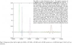
No comment what it captures, but the picture is mirrored. Shapes are OK, but delays are reversed. Someone mirrored the original image. DSD has shortest transition delay and slow PCM (48kHz) digital filter the longest. No one has mentioned?
Hereby the correct picture.
scott wurcer said:
This picture captures all the myth and misconceptions about analog vs digital, truely worth the thousand words.
The stone age.
No comment what it captures, but the picture is mirrored. Shapes are OK, but delays are reversed. Someone mirrored the original image. DSD has shortest transition delay and slow PCM (48kHz) digital filter the longest. No one has mentioned?
Hereby the correct picture.
Attachments
Re: Re: DSD VS assorted PCM impulse response
Good luck Scott. You can lead the horse to water, but you can't force it to drink...
Good end-of-2008 party to all,
Jan Didden
scott wurcer said:
This picture captures all the myth and misconceptions about analog vs digital, truely worth the thousand words.
The stone age.
Good luck Scott. You can lead the horse to water, but you can't force it to drink...
Good end-of-2008 party to all,
Jan Didden
Attachments

SY said:Where do I buy that analog source? Damn, that's God's own tape recorder.
Good point maybe JC could post the impulse response of his best reel to reel.
Re: Re: DSD VS assorted PCM impulse response
The biggest misconception that these pictures capture is the idea that unlabelled oscilloscope traces are definitive when it comes to audibility.
Is the goal making pretty oscilliscope traces or reproducing music?
scott wurcer said:
This picture captures all the myth and misconceptions about analog vs digital, truely worth the thousand words.
The biggest misconception that these pictures capture is the idea that unlabelled oscilloscope traces are definitive when it comes to audibility.
Is the goal making pretty oscilliscope traces or reproducing music?
thank you John! 🙂john curl said:Personally, I almost always use a combination of IC and discrete regulators in series. I use the IC for the nominal voltage setting and hum reduction, and the discrete for transient perfect response and low noise. Works for me!
must be a discrete series regulator then.
Do you have any objections using long tailed pairs in regulators?
Regards
Arny,
Please don't think for a second that you have an exclusive corner on audibility, or put forth the proposition that you have "proof", or the "truth" ok?
There is much to be learned here, even for you.
Put another way, let's not repeat or import the same old agenda from the past and other places?
_-_-bear
syn08 said:
This is what I'm using, with excellent results, to power my PCM1798 D/A setup: http://focus.ti.com/docs/prod/folders/print/tps79133.html TI will send you samples for free if you ask.
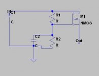
I wonder which regulator is quieter, yours or one like in the attached schematic.
Attachments
- Status
- Not open for further replies.
- Home
- Amplifiers
- Solid State
- John Curl's Blowtorch preamplifier