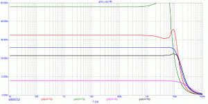
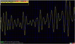
Regarding those opamps, nothing helps them to behave properly (RC at the input). It may be not accidental, that highly ranked OPA627 behaves well.
All of these opamps also show horrible step response (as can be also seen from GD), when input is several ns step, and all of them do not like capacitive load. Again, OPA627 is the exception.
All of these opamps also show horrible step response (as can be also seen from GD), when input is several ns step, and all of them do not like capacitive load. Again, OPA627 is the exception.
Attachments
PMA said:
As usually, you are inverting my words. In known and simple cases, like simple RC, you can derive (meaning deduce) phase response from amplitude response. You cannot do it for unknown circuit.
As usual, you have a hard time explaining what you mean. No, you can not derive the phase response from the amplitude response even for a simple RC circuit. The fact that you know in advance the phase response expression and/or shape for a certain simple circuit is not deriving. Deriving the phase response for an arbitrary circuit can only be done from the complex transfer function.
What kind of experience ..... not every diyer here can see group delay plot from phase plot at first sight.
Why do you speak about audibility? But it is audible, in case that the audio signal is superimposed by HF noise (CD players, HF residuals), depending on circuit it passes through and the circuit that follows.
A high school graduate should have no problem in estimating the derivative of a Ø(w).
Could you please explain why "superimposing HF noise" (BTW, what exactly is that?) can be audible depending on the group delay and what exactly is the involved mechanism? As usual, I would appreciate anything that goes beyond the GEB arguments.
PMA said:Well said.
Amplitude and phase response can be derived from complex transfer function,
Especially for my dear nitpicker syn08.
syn08 said:
As usual, you have a hard time explaining what you mean.
What foreign languages do you speak, syn08. As a Canadien, do you even speak French?? You might have a hard time in foreign language as well.
PMA said:
What foreign languages do you speak, syn08. As a Canadien, do you even speak French?? You might have a hard time in foreign language as well.
I fully agree - it could be a language barrier. The problem is you are making very bold, definitive, authoritative statements which are sometimes either misleading or flat wrong. Read again what you said:
"Amplitude and phase response can be derived from complex transfer function, not always we can derive phase response from amplitude response."
Correct would be:
"Amplitude and phase response can be derived from complex transfer function, we can never derive phase response from amplitude response only."
Because you asked, I am fluent in 4 foreign languages: english, french, german, italian, and can handle bit of spanish. Still, when in doubt, I prefer to spend a little time and polish my phrasing rather than risking to be misunderstood.
PMA said:DSD noise at the ouput of SACD player. Depends on DSD modulator used, differs for various systems and editors.
Output of CD players often contains clock and conversion residuals in the order of 10MHz.
I know you have never explored these signals, syn08.
With all due respect, you know zip about my experience and explorings with such.
You did not answer my question. Don't worry, you don't have to.
PMA said:Regarding those opamps, nothing helps them to behave properly (RC at the input). It may be not accidental, that highly ranked OPA627 behaves well.
All of these opamps also show horrible step response (as can be also seen from GD), when input is several ns step, and all of them do not like capacitive load. Again, OPA627 is the exception.
Hi PMA,
Are those plots from op amp simulations or from op amp measurements?
If they are from measurements, can you show us the corresponding small-signal step response? In other words, even if the rise/fall time of the step is only a couple of ns, I would like to see the step response at a small enough amplitude that there is no slew rate limiting going on.
I think we need to be careful to distinguish linear effects from non-linear effects, but we should not ignore either one of them.
For example, even a Butterworth filter exhibits non-flat group delay, and will not have a perfect step response. However, I would not expect that ideal butterworth filter to worsen the effects of EMI or SACD artefacts.
If you are asserting that non-flat group delay in an op amp makes the presence of such high-frequency garbage sonically worse, what is the mechanism you think is at work? For example, are you assuming a nonlinearity (on that i could certainly agree)?
Thanks,
Bob
Bob,
the plots were simulated. for gain +1, 1k resistor in series with input.
I am aware of the difference of slew rate limited region and small signal region. AFAIK microcap works with "small signal" when calculating AC analysis.
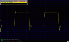
I do not have GD measurement, but can show step responses for many many opamps, taken with generator with rise time shorter than 10ns. Just one for OPA134.
Attachments
What about this one, when R1 and R2 are equal?
An externally hosted image should be here but it was not working when we last tested it.
PMA said:Bob,
the plots were simulated. for gain +1, 1k resistor in series with input.
I am aware of the difference of slew rate limited region and small signal region. AFAIK microcap works with "small signal" when calculating AC analysis.
I do not have GD measurement, but can show step responses for many many opamps, taken with generator with rise time shorter than 10ns. Just one for OPA134.
Hi PMA,
It looks to me that the step response you have shown here is an illustration of the kind of nonlinear behavior that I was seeking to avoid in asking about the small-signal step response. Correct me if I am wrong, but if the waveform you show was entirely within the linear region, the positive-going and negative-going behaviors would be identical.
Cheers,
Bob
syn08 said:
No, you can not derive the phase response from the amplitude response even for a simple RC circuit. The fact that you know in advance the phase response expression and/or shape for a certain simple circuit is not deriving. Deriving the phase response for an arbitrary circuit can only be done from the complex transfer function.
I think I must disagree. For a minimum-phase circuit, the amplitude response and phase response are related by the Hilbert Transform. If you know the amplitude characteristic with sufficient accuracy over a sufficient bandwidth, you can also know the phase response with decent accuracy.
Most of the circuits we are talking about here are minimum phase or at least very good approximations to minimum phase. An all-pass filter is an example of a non-minimum-phase circuit.
There is another way to look at this. If you give me an accurate amplitude response over a given bandwidth, I can plug it into a filter sythesis program to generate a minimum phase circuit that will give that frequency response to within the desired accuracy. I can then obviously simulate that circuit and see its phase response.
37 years ago we were doing this at Bell Labs with the Picturephone analog video repeaters. We equalized a mile of 22 AWG twisted pair with about 60 dB of loss at 1 MHz to within an accuracy of about 0.05 dB out to 1 MHz. Phase response was very important for decent video. We depended on the fact that after you took out flat delay from the line, you were left with a minimum phase equalization function. We then let the IBM 370-168 crank on the synthesis program and out came the needed component values. This technique was called "prescription equalization".
BTW, prescription equalization also depended on a feedback-controlled variable equalizer to keep the equalization right as a function of temperature and other changes. A pilot tone was sent at a frequency just above 1 MHz whose received level was servo'd to be constant by controlling the adjustable equalizer (a so-called Bode Variable Equalizer) with an indirectly-heated thermistor.
Cheers,
Bob
Bob Cordell said:
I think I must disagree. For a minimum-phase circuit, the amplitude response and phase response are related by the Hilbert Transform. If you know the amplitude characteristic with sufficient accuracy over a sufficient bandwidth, you can also know the phase response with decent accuracy.
Once again; can you please would be so kind to draw a phase response from an amplitude characteristic of this thingy?
http://www.diyaudio.com/forums/showthread.php?postid=1627145#post1627145
The problem is in op amp response and its correlation to group delay. Most, and actually almost every op amp circuit is NOT a non-minimum phase shift network. Non-minimum phase networks are NOT what we are talking about here. However, most of us know that feedback amps and servos usually have some excess phase shift, and this is USUALLY tolerated to get maximum speed for the op amp as designed. Have you ever heard of the 135 degree rule?
Group delay is RELATED to the way that the feedback loop is configured, but it is not what we usually look at first. I was attempting to keep everyone, with any technical knowledge, in the loop, rather than get academic, and confuse the situation further.
I must say that anyone with only a high school education, who knows what we are talking about, is either very smart or never has done anything except study. I had a very good time in high school. I didn't learn this stuff until I was well into college.
john curl said:The problem is in op amp response and its correlation to group delay. Most, and actually almost every op amp circuit is NOT a non-minimum phase shift network. Non-minimum phase networks are NOT what we are talking about here. However, most of us know that feedback amps and servos usually have some excess phase shift, and this is USUALLY tolerated to get maximum speed for the op amp as designed. Have you ever heard of the 135 degree rule?
Group delay is RELATED to the way that the feedback loop is configured, but it is not what we usually look at first. I was attempting to keep everyone, with any technical knowledge, in the loop, rather than get academic, and confuse the situation further.
I must say that anyone with only a high school education, who knows what we are talking about, is either very smart or never has done anything except study. I had a very good time in high school. I didn't learn this stuff until I was well into college.
Hi John,
I agree with most of what you said here. However, I think you read me wrong. I did not mean to imply that op amps are non-minimum-phase devices; just the opposite, they are generally a pretty good approximation to minimum phase. I should never have mentioned the all-pass filter as an example of a non-minimum-phase circuit - it apparently led to some confusion.
Cheers,
Bob
Wavebourn said:
Once again; can you please would be so kind to draw a phase response from an amplitude characteristic of this thingy?
http://www.diyaudio.com/forums/showthread.php?postid=1627145#post1627145
That is an all-pass function, which is not minimum-phase, so all that I said does not apply to it.
Cheers,
Bob
Bob Cordell said:
That is an all-pass function, which is not minimum-phase, so all that I said does not apply to it.
Unfortunately, even one common emitter stage has more complex function than a single R-C network. However, my example was very extremal, but the real amp will be somewhere in-between.
Wavebourn said:
Unfortunately, even one common emitter stage has more complex function than a single R-C network. However, my example was very extremal, but the real amp will be somewhere in-between.
I think you are clouding the issue. Just because even one CE stage is more complex than a single R-C network, that certainly does not mean that it is a non-minimum-phase function.
I assume that you do not think that a circuit with more than one pole is a non-minimum-phase circuit. Similarly, just because a circuit has complex poles does not usually make it a non-minimum-phase circuit.
A typical CE stage approximates a minimum phase function quite well over a wide bandwidth. It is true, however, that under some conditions it can go a bit non-minimum-phase at very high frequencies due to the feedforward zero formed by the collector-base capacitance.
Cheers,
Bob
...also, when more than one stages are involved.
I'm not clouding, I'm speaking from high-endish point of view.
My point is, Lumanaw's observation has a rational seed, however it is not the whole story as already had been pointed by folks.
I'm not clouding, I'm speaking from high-endish point of view.
My point is, Lumanaw's observation has a rational seed, however it is not the whole story as already had been pointed by folks.
There's a 10 page thread where Bruno Putzeys mention Group Delay here and there. We can also read his design principle
http://www.diyaudio.com/forums/showthread.php?postid=667085#post667085
http://www.diyaudio.com/forums/showthread.php?postid=667085#post667085
- Status
- Not open for further replies.
- Home
- Amplifiers
- Solid State
- John Curl's Blowtorch preamplifier


