About opamp from that same thread.
Should we look at GD property open loop (before the loop is closed)?A point that has not been highlighted is that any control loop has at least one integrator in it. Typically this will be one with infinite DC gain, also referred to as one pole at DC. The most common example in audio is the op amp. The integrator is formed by the miller capacitance. This means that the loop will have an internal loop phase of 90 degrees. So, any op amp, regardless of how "fast" it is, has a 90º phase shift, open loop, at all frequencies below unity gain, then "group delay" at 20kHz would be 12.5us. I hope you see the absurdity of taking this phase shift for "delay". To speak of "delay" or "group delay" outside the flat portion of a filter response is a good way of becoming very, very confused (see digression at the end). When something happens, the output of the integrator responds immediately. When we close the loop, we find that at frequencies where loop gain is high, closed-loop phase shift is now very small, and so is closed-loop group delay (which is now again a sensible notion because the amplitude response is flat).
Lumanauw, we need something more clear to discuss. This is a waste of time, in the way that we are discussing it now. First, we have to separate class D from analog. They have completely different design tradeoffs. Then we have to look at stability, and perhaps look at ringing and settling time. These ARE important parameters. Group delay well reflect the potential for instability, and MAYBE it can even tell us something even more meaningful, BUT not with the information that we are tossing around at the moment. I agree with Bob Cordell in this. Discussing group delay as we are is just 'clouding the issue'.
Bob,
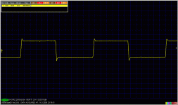
some opamps have never identical rise and decay part of unity gain step response, they are never linear for high frequencies, even for small signals. OPA134 is the one. You can mask this be preceding RC, or by reduction of generator slope.
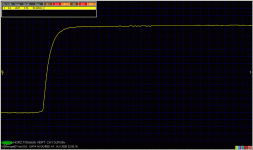
For OPA627 we get better behaviour-attached.
The results shown were one of the reason why I moved to discrete circuits and insist on consistent step response for ALL amplitudes. The other reason, more important, is the sound 😉
some opamps have never identical rise and decay part of unity gain step response, they are never linear for high frequencies, even for small signals. OPA134 is the one. You can mask this be preceding RC, or by reduction of generator slope.
For OPA627 we get better behaviour-attached.
The results shown were one of the reason why I moved to discrete circuits and insist on consistent step response for ALL amplitudes. The other reason, more important, is the sound 😉
Attachments
Well stated, PMA. I am learning a trick or two, myself. I use OPA134 devices for servos and other things, along with the AD797. However, I try to stay from unity gain op amp operation in audio circuits.
I hope to have some preview versions of OPA1611 to play with soon... Results will be reported.
I try to stay from unity gain op amp operation in audio circuits.
Precisamundo !
My best ever (RIAA) preamp was with a 5534
set for both phono pre and line gain @ 1kHz
I.E. ~ 50db gain @ 1 kHz with corresponding
compensation with a single op-amp
Precisamundo !
My best ever (RIAA) preamp was with a 5534
set for both phono pre and line gain @ 1kHz
I.E. ~ 50db gain @ 1 kHz with corresponding
compensation with a single op-amp
If it was feedback RIAA circuit, it would have unity gain, in other words, any integrator MUST be unity gain stable. So, for any C in feedback (without series resistor), your opamp MUST be unity gain stable. The OPA134 is declared to be UG stable, but we have seen how.
Bob Cordell said:
I think I must disagree. For a minimum-phase circuit, the amplitude response and phase response are related by the Hilbert Transform. If you know the amplitude characteristic with sufficient accuracy over a sufficient bandwidth, you can also know the phase response with decent accuracy.
Most of the circuits we are talking about here are minimum phase or at least very good approximations to minimum phase. An all-pass filter is an example of a non-minimum-phase circuit.
Bob,
This is rather academic, however: assuming the circuits is minimum phase, that is, linear and time invariant, is a pretty rough approximation of any audio circuit, at least at the level of linearity we are talking here. Assuming the amplitude and phase are conjugate functions (and also Titchmarsh's theorem applies) may or may not be a valid hypothesis. I was talking about the general case.
Hi, Mr. Curl,
I've been shown an "OK" gain(dB)+phase(deg) graph of an amp (no sign of instability, but not so nice sounding), can actually have "not OK" GD and NG graph.
But on opposite direction, "OK" GD and NG graph always have "OK" gain+phase graph. And "OK" sound too.
Making a classD amp really strengthen analog design skill, I can assure that.
You're right on spot. Group Delay and Noise Gain graph can easily show instability, compared if we look at gain graph or phase graph.Then we have to look at stability, and perhaps look at ringing and settling time. These ARE important parameters. Group delay well reflect the potential for instability,
I've been shown an "OK" gain(dB)+phase(deg) graph of an amp (no sign of instability, but not so nice sounding), can actually have "not OK" GD and NG graph.
But on opposite direction, "OK" GD and NG graph always have "OK" gain+phase graph. And "OK" sound too.
I agreeand MAYBE it can even tell us something even more meaningful, BUT not with the information that we are tossing around at the moment. I agree with Bob Cordell in this. Discussing group delay as we are is just 'clouding the issue'.
I'll have to agree with Bruno Putzeys on this one. He wrote an article "All Amps are Analog" (AES Paper 353, 20-23 May Paris, France). ClassD amps are analog amps, the problems are analog problems. The design goals also analog ones (targeted frequency response, THD, noise). To cure the problems, analog cure.First, we have to separate class D from analog. They have completely different design tradeoffs
Making a classD amp really strengthen analog design skill, I can assure that.
you are deliberatly pushing the OPA134 with 200V/us which is way outside the specs of this part.PMA said:
some opamps have never identical rise and decay part of unity gain step response, they are never linear for high frequencies, even for small signals. OPA134 is the one. You can mask this be preceding RC, or by reduction of generator slope.
For OPA627 we get better behaviour-attached.
The results shown were one of the reason why I moved to discrete circuits and insist on consistent step response for ALL amplitudes. The other reason, more important, is the sound 😉
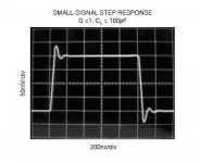
But the OP recovers from this kick in app. 0,2us! 😱
Something you haven't mentioned and what seems quite impressive to me. 🙂
regards
no, group delay is only important for the complete amplifier and easily achieved. Even with this evil 90° open loop phase shift. Input and output from most amplifiers are in phase inside and way beyond the audio band.lumanauw said:About opamp from that same thread.
Should we look at GD property open loop (before the loop is closed)?
regards
Juergen Knoop said:
you are deliberatly pushing the OPA134 with 200V/us which is way outside the specs of this part.
Intentionally. HF EMI and RFI does not ask us, if we are out of specs. And the datasheet does not say we must not use fast input slope.
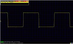
We get this from datasheets, which is no way true for 100pF cap load. Maybe they use variable slope generator to get nice pictures?
Attachments
I don't see a large difference to your measurement.
Small differences from experimenter to experimenter or between equipment/parts are quite normal when doing experimental stuff. 🙂
regards
Small differences from experimenter to experimenter or between equipment/parts are quite normal when doing experimental stuff. 🙂
RF could be filtered out prior to the amp. I see this more as a circuit design issue, than as a part property.Intentionally. HF EMI and RFI does not ask us, if we are out of specs.
regards
Juergen Knoop said:I don't see a large difference to your measurement.
Small differences from experimenter to experimenter or between equipment/parts are quite normal when doing experimental stuff. 🙂
RF could be filtered out prior to the amp. I see this more as a circuit design issue, than as a part property.
regards
There is a difference, as my measurement has different positive and negative overshoot (for OPA134, and not for OPA627). I would vote for lower slope derivative in their meas.
"RF could be filtered out prior to the amp" - only in case you fulfill design rules of HF instruments. Almost no audio gear does, and there are many ways how RF/HF spreads through poorly HF designed instrument. Forget simple RC somewhere, it is easily bypassed.
maybe, you are using a different generator etc.There is a difference, as my measurement has different positive and negative overshoot (for OPA134, and not for OPA627). I would vote for lower slope derivative in their meas.
So I wouldn't expect any measurement exactly equal.
My point would be, that this cheap OPA doesn't perform bad.
Of course there are better, more expensive OPs available and some people even build discrete designs with fare more superior step responses. 😉

regards
PMA said:
There is a difference, as my measurement has different positive and negative overshoot (for OPA134, and not for OPA627). I would vote for lower slope derivative in their meas.
A shy question: when measuring at such high speeds, have you properly terminated the coax? The HF pulse response depends dramatically on the coax impedance matching at both ends. I recall testing OPA134 step response but I don't recall this kind of overshoot response (maybe I didn't push it that far).
But then I still need to understand why such effects are important in audio and why input HF filtering is not good enough.
From this point of wiev(step response) it is (IMHO) much better to use OPA in inverting configuration.
syn08 said:
A shy question: when measuring at such high speeds, have you properly terminated the coax? The HF pulse response depends dramatically on the coax impedance matching at both ends.
Well - fast measurement in time domain is a part of my professional job.
I have made several independent set of measurements, with 2 generators, Tek 2445B scope, and USB digitizer (pictures shown). Tek and digitizer results were same.
Output of opamps were measured in 3 ways:
1) oscilloscope probe, 10M//23pF (results shown here)
2) 50R resistor + 1m RG-58, no termination - many opamps become instable
3) 50R + RG-58 + 50R terminator, low amplitudes, because of current requirements. Some opamps, like LT1122, cannot handle this, unable to source transient current into 100R
LM6171, just to show quite perfect behaviour in time domain:
Attachments
- Status
- Not open for further replies.
- Home
- Amplifiers
- Solid State
- John Curl's Blowtorch preamplifier