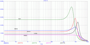
PMA, this seems fairly normal to me. However, are these curves done at unity gain? If so, then this is the problem, more or less. Dimitri thinks that Bruno is really talking about Class D output filters. What is he specifically referring to?
Hi, PMA,
What circuit graph is that? Is the Y axis = time(second)? I notice the OPA627 has no peaking. NE5532 has moderate peaking, but OPA134 like TL071 has high peaking.
Hi, Mr. Curl,
Bruno's opinion about constant group delay is not only for classD amps. It can be seen at his analog amp design too. http://media.hardwareanalysis.com/articles/large/11997.gif Folded cascode front end, heavy biased output stage, and NP's SuSy feedback.
Hi, PMA,
Do you have simulation graph for group delay of Blowtorch-estimate? I would guess it has flat group delay curve.
Do you have simulation graph for group delay of Blowtorch-estimate? I would guess it has flat group delay curve.
john curl said:PMA, this seems fairly normal to me. However, are these curves done at unity gain? If so, then this is the problem, more or less. Dimitri thinks that Bruno is really talking about Class D output filters. What is he specifically referring to?
Yes, at unity gain. This is the worst possible condition, regarding HF stability. The opamps have 1k in series with +IN, no cap.
Pavel,
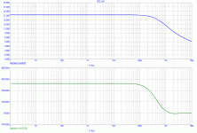
With reference to your GD BT2 simulation, I was in the assumption that the BT gain is 8 dB Single Ended and 14 dB Balanced. Your frequency-plot shows 21 dB, probably balanced. Please correct me if I'm wrong.
With reference to your GD BT2 simulation, I was in the assumption that the BT gain is 8 dB Single Ended and 14 dB Balanced. Your frequency-plot shows 21 dB, probably balanced. Please correct me if I'm wrong.
The curve for the CTC is essentially the same in any case. How could it be different? There is no global feedback to cause instability or ringing.
Hi, PMA,
Is there a way to get actual GD graph from a real amp, that I can do at home? I've got soundcard and measurement program, oscilloscope, signal generator.
Is there a way to get actual GD graph from a real amp, that I can do at home? I've got soundcard and measurement program, oscilloscope, signal generator.
Hi, Mr. Curl,
I think it is not only instability or ringing. I'm no expert in signal transfer like PMA, but from computer simulation, feedback and non-feedback make big difference in Group Delay and Noise Gain graphs. Without feedback, I cannot make peaks with these 2 graphs. Peaks within these graphs can only occur when there is feedback applied.
And we can design feedback amp (in simulator) that have flat graphs like non-feedback amps.
There is no global feedback to cause instability or ringing.
I think it is not only instability or ringing. I'm no expert in signal transfer like PMA, but from computer simulation, feedback and non-feedback make big difference in Group Delay and Noise Gain graphs. Without feedback, I cannot make peaks with these 2 graphs. Peaks within these graphs can only occur when there is feedback applied.
And we can design feedback amp (in simulator) that have flat graphs like non-feedback amps.
Hi Lumanauw,
group delay is a derivative of phase response. Some basics is here:
http://en.wikipedia.org/wiki/Group_delay
Regarding non-global feedback amp, it may have wild GD plot, in case there is a kind of instability.
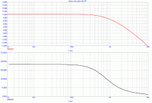
You can get nice GD even from power amp. On the other hand, opamp examples with GD peaking shown hereabove, cannot be simply corrected by inserting RC element in front of them. This RC would increase GD for low frequencies, BUT when magnifying HF portion of the plot, the peak remains.
Actually, this appears to be leading nowhere. Group delay is derived from phase shift with frequency, which is derived from amplitude change with frequency (much of the time). (I think) So what?
We all know that LRC circuits and active feedback circuits will change the frequency response of a circuit, and often make it overshoot and ring. IF we try to get the best or flattest group delay, we usually have to slow down the maximum available speed of a given circuit. What can anyone afford? Until I see some real info from Bruno as to what he is concerned with, and WHY, I think we are just confusing approaches to optimum audio design, speculating about it.
We all know that LRC circuits and active feedback circuits will change the frequency response of a circuit, and often make it overshoot and ring. IF we try to get the best or flattest group delay, we usually have to slow down the maximum available speed of a given circuit. What can anyone afford? Until I see some real info from Bruno as to what he is concerned with, and WHY, I think we are just confusing approaches to optimum audio design, speculating about it.
Well said.
Amplitude and phase response can be derived from complex transfer function, not always we can derive phase response from amplitude response.
Amplitude and phase response make complete description of a LINEAR circuit, as well as impulse time response does.
To see (imagine) group delay from phase response is only a question of experience, and group delay is not so widely used as phase response, that is why it may seem less familiar for some fellow audioholics.
PMA said:Well said.
Amplitude and phase response can be derived from complex transfer function, not always we can derive phase response from amplitude response.
To see (imagine) group delay from phase response is only a question of experience, and group delay is not so widely used as phase response, that is why it may seem less familiar for some fellow audioholics.
I'm on vacation across Europe but I can't resist this one 😀
Can you show us an example of deriving the phase response from the amplitude response?
What kind of experience would one need to "see (imagine)" the group delay? Last time I've checked, the group delay is -dØ/dw and any decent vector analyzer can measure this, as much as the phase delay. An analytical approach is also possible but it is, in real life, complicated even for linear circuits.
This is not about the audibility of the group delay (which I believe it is zip, nada, JS).
john curl said:Actually, this appears to be leading nowhere. Group delay is derived from phase shift with frequency, which is derived from amplitude change with frequency (much of the time). (I think) So what?
We all know that LRC circuits and active feedback circuits will change the frequency response of a circuit, and often make it overshoot and ring. IF we try to get the best or flattest group delay, we usually have to slow down the maximum available speed of a given circuit. What can anyone afford? Until I see some real info from Bruno as to what he is concerned with, and WHY, I think we are just confusing approaches to optimum audio design, speculating about it.
Hi John,
I agree, at least for "minimum phase" circuits the amplitude, phase and group delay responses are tightly linked. And I think most power amps are a fairly reasonable approximation to minimum phase across most of their band.
The thing I wonder about is how we should "grade" group delay response graphs in terms of inferred sonics. For example, most of those op amps in #9681 looked pretty terrible in terms of group delay peaking, if I interpreted them right. However, note that the baseline group delay was quite small, less than about 31 ns for all of them. Moreover, even the TL071's group delay was constant within 1 ns out to 1 MHz. The NE5532 was constant at about 15 ns within 1 ns out to about 3 MHz.
On the other hand, the "good one" in one of the later posts did not peak at all, but it had a baseline group delay of a couple hundred ns and departed by 1 ns by about 100 kHz. So, even though the plotted shapes looked very different, I'm not sure which one would be considered objectively better for audio. I would tend to think that the absolute amount of time delay departure, and how high the frequency was where it took place, might be the criteria. If the group delay is constant within 1 ns out to 1 MHz, and then peaks by 10-20 ns by the time it gets to 10 Mhz, is that better? I'm not sure.
I'm certainly not defending the TL071 here, just wondering if the initially apparent peakiness in group delay above 1 MHz has anything to do with audibility. Indeed, when I first looked at the graph I though it was amplitude peaking, which would have been terrible and quite another kettle of fish.
Cheers,
Bob
syn08 said:
I'm on vacation across Europe but I can't resist this one 😀
Can you show us an example of deriving the phase response from the amplitude response?
What kind of experience would one need to "see (imagine)" the group delay? Last time I've checked, the group delay is -dØ/dw and any decent vector analyzer can measure this, as much as the phase delay. An analytical approach is also possible but it is, in real life, complicated even for linear circuits.
This is not about the audibility of the group delay (which I believe it is zip, nada, JS).
As usually, you are inverting my words. In known and simple cases, like simple RC, you can derive (meaning deduce) phase response from amplitude response. You cannot do it for unknown circuit.
What kind of experience ..... not every diyer here can see group delay plot from phase plot at first sight.
Why do you speak about audibility? But it is audible, in case that the audio signal is superimposed by HF noise (CD players, HF residuals), depending on circuit it passes through and the circuit that follows.
Bob,
think about EMI, RFI issues, DSD noise, D/A residuals. IMHO this is more important than properties in audio band, which are easily achieved excellent.
think about EMI, RFI issues, DSD noise, D/A residuals. IMHO this is more important than properties in audio band, which are easily achieved excellent.
- Status
- Not open for further replies.
- Home
- Amplifiers
- Solid State
- John Curl's Blowtorch preamplifier


