So in my case I have a 55pF capsule
In this case 2SK170 input capacitance is not that important. I remember that you mentioned that yoor preamp is for small mike, I thought you are working with capsules of 10 pF.
Scott, I have primarily worked with 1/2" 19pf mikes, and input levels up to 154 SPL due to close trumpet miking. I agree that larger area mikes of 60pf or more, or the Panasonic mikes are easier to load and the noise losses are less obvious, but to me, that is like comparing an SUV to a sports car. I'm interested in putting forth any tradeoffs, AND their relative magnitude on this thread, rather than putting them 'under the table', so to speak. You never know, someone reading this thread might just be trying to make a SOTA microphone preamp in future. It would be unfortunate if they were mislead into using a compromised solution, because they did not know any different.
It is totally different than M7 capsule used for concerts with voices accompanied by acoustic guitars. 80 pF and 70 dB SPL. Do you hear me now?
And again, how can you speak about "compromised solutions" working in the field that all consists of compromises? Did you ever heard of such a basic for an electronics design word optimization?
I doubt now...
Edit: if you are going to continue teaching readers orthodoxly religious approach to design you have to teach them to orthodoxly religious approach of promotion of it's results. I don't want to participate in such an activity.
Everything that you do design seems to be 'compromised' Wavebourn. However, I like to concentrate on best-of-best, not what I did last week in order to make something work.
john curl said:Everything that you do design seems to be 'compromised' Wavebourn. However, I like to concentrate on best-of-best, not what I did last week in order to make something work.
Yep, all my designs are compromised: I was thoroughly taught to optimize.
Uncompromised JC stuff should have zero noise, zero output impedance, infinite input impedance, zero power consumption, zero weight, zero size, zero cost. While you have no such amps, all your amps are compromised.
By the way, I would be a big pig if started to review your IRF610 with huge input dynamic capacitances driven by a poor diffcascade...
Good luck!
There is no danger in some little noise.
Even in our higher gain mic amps.
1. Microphones have noise levels
2. and so have most any alive non-artificial recording room.
3. and the sound material you record will have noise.
As long as the resulting noise in your speakers
in your playback situation
4. is not way above the background noise in your listening position
.. you can stop worrying.
5. Besides, most speakers have a natural roll off freq, at about 15 kHz
6. And the air in one room acts as a sort of acoustic filter for sound waves
7. before they reach your inherit noise in your own ears' cabinet.
Come on!
These endless noise discussions
is like constantly day in and day out
be discussing what food the astronauts
should have along with them,
when go for the future travel to our nearest neighbour starsystem:
= 4 lightyears away from here.
Lineup 🙂 tired of all that noise about all this noise
Lineup, please be more accurate in what you print about me. You have made serious mistakes so far on your website, and I hold you accountable.
Well, what have we commented on about microphones, and how can we sum it up?
First, there are different size microphones from about 1 inch in diameter to as small as 1/4 inch in diameter for recording audio sounds. There is a BIG tradeoff with high frequency fidelity when you use a large area mike, but for an individual singer, or instrument, it can be fairly accurate. Smaller diameter mikes are more extended in high frequency response, both on and off axis, but they are noisier, unless you are very careful, and they generate distortion just from being loaded with a capacitance, whether on purpose, or due to engineering oversight.
Now, if you don't care much, then just about any high impedance circuit will, more or less, work. If you want to make a state of the art microphone design, you have to be very careful, more careful than several of the examples shown on this thread, so far.
It is a bit like using IC op amps. You can use almost any IC op amp that has been available for the last 42 years to amplify audio. It is just that some IC op amps work better than others in many specific applications, BUT if you want, you can use a bipolar input op amp with source impedances over 10Kohms or use a jfet input op amp as a moving coil input. It is just that they are not the best possible choices for those specific applications.
It is the same for condenser microphone input stages.
Now what jfets may be best for condenser microphone inputs?
There is a conflicting set of parameters that make it more difficult to pick an 'optimum' input jfet. One is low frequency noise, and hi Gm (they tend to go together, at midrange frequencies at least) and very low input capacitance, which is composed of both the drain-to-gate and the source-to-gate capacitance together. These capacitances can be found on the data sheets, and they are DC voltage sensitive, so power supply voltages are also important, both in a good way, but also in a bad way. In order to get a specific jfet to have a minimal interaction, or not adding both noise and distortion: bootstrapping and cascoding techniques should be employed. You won't find this in cheap designs.
Now what about specific devices? Well, the 2N4416, one of the first jfets, has worked well for me, and the Sony 2SK152 is excellent. Interestingly enough, Scott Wurcer's contribution, the Phillips BF862 looks pretty good too, especially with larger area mikes.
Now, what is the downside of these particular fets? One, they don't like too much voltage across them, so you must cascode with another fet, or work at low voltages. A 48V phantom supply is a little scary, without a cascode, but a 12V remote supply might be OK.
You can actually see a breakpoint in drain-to-gate leakage at voltages of 10V or less. RF fets like the 4416 can be even MORE sensitive to this. So, you might get low input capacitance, but if you use it wrong, you will pay plenty in input leakage.
Now where did the Sony 2SK152 come from? Well, it is one of the highest Q devices ever made. Q in this case is defined as Gm/Cin. In other words, for a given Cin you have the most Gm which implies low noise. However, this device is NOT perfect. It does have some 1/f noise, just like the BF862, and this makes it troublesome for some applications, but still OK for microphone applications.
Finally, what about the 2SK170? It is a very good device, BUT it is not the best for most condenser microphone inputs, because it has 3-10 times the capacitance that the other specified devices have, mentioned here. That is why a brought the subject up.
Hello Mr. Curl,
Recently I had made a Pass B1 line level 22k volume pot buffer, in a symmetrical PSU version without coupling capacitors. The pot is wired before the buffer. Its a simple source follower tied with an Idss current source underneath, using the same FET. The output offset stays vanishingly low with very well matched FETs. I had subjectively found that with 10V across 2SK170BL (7mA Idss matched pair, 12mA idle) the sound was considerably smoother than with even 9V or 11V. Could there be an objective reason for that ''sweet spot''?. Also what voltage would you consider optimum across the 2SK170BL for 4-5mA idle in common source mode?
Thank you in advance,
Salas.
Attachments
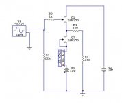
Salas, what you are using is almost exactly the circuit that Bob Crump used, at my suggestion, before we went forth to make the CTC preamp.
I personally like this follower, and it makes a great pot buffer. However, normally we would use perhaps +/- 15V rather than +/- 10V, but we would also use 10 ohm source resistors that would reduce the Id slightly.
Your 'sweet spot' may be related to operating the devices at Idss, but I can't be sure. Certainly, leakage (not too important here), self heating (reduces Gm), nonlinear input capacitance (amount and rate of change with input voltage) are all factors that contribute. You apparently have hit a 'sweet spot' and I would keep it, but I don't know if you will repeat it with another Idss. You will just have to try. 10V across each device is a very comfortable place, because the rate of the [input capacitance rate of change with voltage] at about 10V, yet the leakage has not taken off with voltage across the gate. However, it could be too much voltage with a microphone stage, especially with an optimized jfet at very high source impedances. Then we must make another set of tradeoffs.
Thank you for your prompt answer.
Relating to certain Idss was my uneducated guess, started at +/-15V but it was surely harsher. I picked 7mA Idss because my stash of BLs and those of a couple of friends average 7-8mA Idss for maybe 60-70% of the lot. So I thought it better be easily repeatable. Where about in voltage across a common source 7mA Idss 170BL running at 4-5mA, the leakage may roughly occur? If you had some incident or looked for that data of course.
Relating to certain Idss was my uneducated guess, started at +/-15V but it was surely harsher. I picked 7mA Idss because my stash of BLs and those of a couple of friends average 7-8mA Idss for maybe 60-70% of the lot. So I thought it better be easily repeatable. Where about in voltage across a common source 7mA Idss 170BL running at 4-5mA, the leakage may roughly occur? If you had some incident or looked for that data of course.
Actually, leakage of the 170 class jfets doesn't really start until you reach 8V, so you might as well use at least that. However at 10 volts, the leakage is 10 times worse than 8V and so forth, so you don't want to go too high, unless you have an extra low impedance drive source.
Thank you. I will always use a variable regulated supply and check for best performance and Vd I guess, especially if the sources are moving coil cartridges which are 6-20 Ohm sources many times.
I did not state the voltage problem as clearly as I wish that I could. You have several tradeoffs: noise, circuit stability, distortion, max output swing. They all conflict with each other to some degree. Some leakage is tolerable IF the circuit is line level in operation and the input source resistance is below 100K ohms or so. However, with moving coil levels, you have to be more careful because the leakage is prone to add noise.
For microphone circuits that have 1000 meg ohms or more input impedance, you have to be extra careful with leakage, because the input resistor will have to drop voltage across it, in order to drain the leakage to ground. This could cause EXCESS NOISE in the resistor and add to the input noise of the circuit. It pays to be careful, to get best results.
For microphone circuits that have 1000 meg ohms or more input impedance, you have to be extra careful with leakage, because the input resistor will have to drop voltage across it, in order to drain the leakage to ground. This could cause EXCESS NOISE in the resistor and add to the input noise of the circuit. It pays to be careful, to get best results.
No 1000 Meg in a large diaphragm condenser microphone. On 1 KHz it's capsule has about 2 megaOhm capacitive impedance. I've already disclosed on this forum lot of original design ideas that may be used to build very good stuff, when well understood how they work, and how to improve them.
Speaking of improvements, once about 30 years ago one smart theoretician laughed about my amp and suggested to the owner to make it better. He removed resistor from class A driver to output, reduced it's current, added bias to output transistors through Vbe multiplier with thermal feedback, removed some "odd" feedbacks, and got worse sound. Actually he turned my amp with class A+C approximation of transfer function with no crossover region on zero crossing to the ordinary plain class AB opamp. The next day the amp blew up output transistors during the concert, so the owner went back to me with apologies.
Speaking of improvements, once about 30 years ago one smart theoretician laughed about my amp and suggested to the owner to make it better. He removed resistor from class A driver to output, reduced it's current, added bias to output transistors through Vbe multiplier with thermal feedback, removed some "odd" feedbacks, and got worse sound. Actually he turned my amp with class A+C approximation of transfer function with no crossover region on zero crossing to the ordinary plain class AB opamp. The next day the amp blew up output transistors during the concert, so the owner went back to me with apologies.
Wavebourn, you are confusing the issue. At DC the impedance is 1 Gig ohm or so. In fact, YOUR design is the very worst of the examples presented, in regards to input leakage, as was brought out by Dimitri. When are YOU going to listen and learn a thing or two? You could, with the addition of just one cheap jfet, remove the significant voltage across your input jfet, by cascoding it. Have you ever looked carefully at the spec sheet of the 2SK170? What about input leakage vs voltage? I am not here to criticize you specifically, but I try to point out what problems exist in many designs, both commercial and amateur, in order to promote the best audio design possible.
John,
the term Impedance means a complex resistance.
DC resistance is a resistive part of impedance.
Also, resistance may be static and dynamic.
What we must consider the most in condenser microphones, is a non-linear dynamic impedance both in the capsule and in the amp.
Edit: Good luck to both you and Dmitri to improve my design, but don't blame on me if after improvements they sound worse, or depends more on powering voltage, or are unaffordable for ordinary performers, and so on...
For the benefit of everyone, let me put forth what we are talking about and why we use such high resistance input bias resistors.
First, realistically, we have to use high value resistors to get low frequency response as we are coupling with such a low capacitance 15-100pf, normally. This gives a minimum coupling resistance of about 100 million ohms. Why not stop there? Well, the resistor, itself makes noise, even if there is no DC voltage drop across it, and a 100 meg ohm resistor makes lots of noise. However, the microphone capacitance actually LOWERS the noise by shunting the noise to ground through the mike. This reduces the audio noise considerably, especially above a few hundred Hz when the ear becomes most sensitive.
Now what happens when we use 1 billion ohms, or a 1000 megohms, or a 1G resistor? (these are all the same value) The noise actually DROPS because even though the resistor itself actually makes even more noise, because it is coupled to ground even better. Therefore, a 1G resistor has 10 dB less noise when coupled with a microphone or an equivalent capacitance.
Now, let us look at leakage from a 2SK170 fet, and the DC voltage drop across a 1G resistor.
At 8V across the jfet, we get 1 picro-amp, at 10V 10 picro-amps, at 13V 100 picro-amps, at 16V 1 nano-amp, at 22V, 10 nano-amp.
What is important is to note the working voltage of the input device and its leakage. If the leakage is too much, then DC voltage drop will appear across the input resistor. Is this good? Is it important? It partially depends on the characteristics of the input resistor. If it is prone to excess noise then extra noise will be produced.
If we wanted to fix this problem easily, how would we do it as easily as possible? It so happens that a long gate, high Idss device could be added across the input fet without adding any other part, and reduce the input leakage by many decades.
That is what we are discussing. Is it worth it?
May be a cascode would be a good idea to solve a noise problem if we had it, if an additional transistor don't add distortions, phase shifts on highs, own noises... But what to solve if the problem is theoretical only?
By the way, I feel a De-Ja-Vu now... 30 years ago one Doctor of Science said that I should not be allowed to come to an electronics design close than an artillery shot... You know why? Because he badly wanted the Soviet Science and Engineering to be The Superior, while I used medium power transistors in dynamic mic pres! I was called stupid and under-educated. 😀
I did not care; my mic pres sounded less noisy and more musical than all the rest in the world.
Edit: recently one of my friends, famous retired designer of VGA cards, said that I must implement a ground plan, because traces going to my star ground according to his famous opinion were too thin... Can you imagine what could happen if I listening to his legendary opinion combined together an input ground and a power supply ground in a single ground plan?
- Status
- Not open for further replies.
- Home
- Amplifiers
- Solid State
- John Curl's Blowtorch preamplifier