fair use permits the excerpting of copyrighted materials, afaik...
_-_-bear
PS. I am now seated, John... 😉
_-_-bear
PS. I am now seated, John... 😉
Thanks Bear, it would be helpful if the equation for mike cap distortion could be put up so that we could all look at it.
You may be right, Wavebourn, but B&K is perhaps a little more, up-to-date. On their website, they revise certain older equations. I don't know if it is the one that you quoted. I will try to check.
Please compare your equation with the results shown in the 'B&K Technical Review' Vol 3 July 1955. I think that you will find it useful.
Please compare your equation with the results shown in the 'B&K Technical Review' Vol 3 July 1955. I think that you will find it useful.
In a month I will most probably have a chance to hear Halo JC-2, and to compare with my preamp. If everything goes OK, there will be a JC poweramp as well.
Of course, the JC-2 is not my best effort. I have a feeling that what you have already is pretty darn good. One tradeoff in making a commercial product is the attention to subtle detail (often disregarded by many of our critics) that cannot be added to the best designs when fabricated by others.
You know, I am looking forward to hear it very much. Such experience can not be compared to paperwork 😉 . It is out of our possibilities and abilities to get the CTC Blowtorch. I wish the poweramp was JC-1. I will let you know, of course.
john curl said:You may be right, Wavebourn, but B&K is perhaps a little more, up-to-date. On their website, they revise certain older equations. I don't know if it is the one that you quoted. I will try to check.
Please compare your equation with the results shown in the 'B&K Technical Review' Vol 3 July 1955. I think that you will find it useful.
Thank you John for the e-mail;
unfortunately I have to disagree with author's statement that with zero stray capacitance there are no distortions at all: it is against laws of physics, please see equations I've posted before, they are basic for physics of capacitance.
Edit: equations even don't assume non-linear tension and non-flat displacements of a membrane.
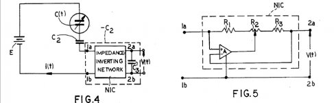
dimitri said:That is why Frederiksen idea have never been patented:
http://www.pat2pdf.org/patents/pat4281221.pdf
The drawings are strange (some parts are in series instead of parallel), but text is ok
This certainly can’t work. Where does the noise of R1 (expressed as an equivalent current noise) go? Why are the impedance levels G-Ohm in microphones, remind us John?
Is there an engineer in the house?
Attachments
PMA said:You know, I am looking forward to hear it very much.
Any prizes for those who already guessed the results? 😀 😀 😀
Wavebourn said:
Thank you John for the e-mail;
unfortunately I have to disagree with author's statement that with zero stray capacitance there are no distortions at all: it is against laws of physics, please see equations I've posted before, they are basic for physics of capacitance.
Edit: equations even don't assume non-linear tension and non-flat displacements of a membrane.
What is funny if to read the paper more deeply, in one place he writes that the ratio between displacement and diameter is negligible, in another part he writes that capacitance variations caused by such displacement are the main factor of distortions, but only when capacitive loaded.
We used to write papers with lot of formulas (the more the better - less chance they will be carefully read and understood) for our management to get financing of new R/D themes in order to satisfy own curiosity for company's expenses. Main needs had to be put at the top and at the end of the paper to be understood and addressed. This paper would be great to get better more expensive FETs and double diaphragm capsules.
What is true, double diaphragm capsules help to reduce 2'nd order harmonic that is significant for microphones made to measure high SPLs, but our ears don't act such a way despite we have 2 of them.
Scott, I try to do the best that I can. It doesn't mean that I don't make mistakes, or that you don't make mistakes either. I try to promote, especially on this thread, the best of the best: ideas, topologies, and mathematical formulas.
Week-end amateur projects usually are flawed in some ways, but then who cares for the most part? Only on this thread do I really try to keep it as fresh and advanced as possible, no matter what we are designing. That is, to me, the only way that we can do to improve audio electronics, and to pass useful information known only by serious audio engineers.
For example, your cap feedback is noted and understood, BUT does it cause problems outside the normal analysis? B&K would have used this approach, long ago, if that were not the case, I would think. I can be shown to be wrong, but please show me, rather than ignore B&K's analysis.
I DO KNOW that the popular passive attenuator, used by MANY microphone manufacturers, using a cap across the capsule, DOES cause added distortion. John Meyer and I measured it, decades ago, on our own. What makes your approach immune from this distortion increase?
john curl said:I DO KNOW that the popular passive attenuator, used by MANY microphone manufacturers, using a cap across the capsule, DOES cause added distortion. John Meyer and I measured it, decades ago, on our own. What makes your approach immune from this distortion increase?
I never made any claims about distortion. In fact I have not yet made the analysis, because as you must realize the gain in my way is cut by increasing the feedback capacitance not by paralleling the capsule. I only said that I can get the benefit of the low noise of a 2SK170 without the penalty of the Crss, this I have measured. There is certainly no reason the distortion is any worse. But it's not my way as I have found Neumann, AKG, and others have used it. B&K's analysis is for the charge Qo held constant as in the voltage mode of operation. I have not found an analysis for current mode operation and don't have the inclination to do it myself. B&K is in the business of making traceable standard instruments not necessarily musical ones.
BTW Dimitri, B&K does have a patent on their method, the other patent has so much noise, as shown, it is useless. Also the computation of optimum compensation have little or nothing to do each other. In fact it has to do with a fairly complex geometrical analysis of a flexing membrane fixed at the edges and nothing like putting a negative Co in series with the capsule (Co). His negative capacitance is also made in a way that could add little or no noise.
From Herr Frederiksen's paper...
The idea (patented) of using negative input capacitance for distortion reduction
seems to work well in practice but further experiments have to be made to
clarify all aspects of its use.
Ooops to late to edit but one more from Herr Frederiksen's paper...
At higher frequencies
the air damping and the foil mass do also influence the mode. This discussion
covers only the low frequency mode which can be considered to occur up
to a frequency which is 0.2 to 0.5 times the diaphragm resonance frequency.
So the distortion reduction technique is only for the low frequency end.
I wanted to ask for the B&K paper, but thanks Scott for the analysis, it is also useless, as the AES one John sent me...
I spent until 2AM reading the B&K paper, it is great stuff but as these things go if you read and at least sort of understand you tend to pick and choose what you want to hear. He talks about 140dB SPL that's 10V! right out of the capsule. So I apologize John, if you want to mic a kick drum from 6" you are right. We are just comparing apples and oranges. I don't want to stop down the mic I want to boost it.
I thought he AES paper was about dipole vs monopole transduction? The planar speaker guys know all about this. So it's best not to knock anything without reading and understanding.
Herr Frederiksen's paper is the one worth a read, there is even a nice graph of the results. But there was an AudioXpress article comparing a B&K capsule to a $1 Panasonic from Digikey with the source follower mod and the distortion even at 130dB was comparable. So let's drop the distraction and get back to the Blowtorch.
http://www.audioxpress.com/magsdirx/ax/addenda/media/danavaras2861.pdf
BTW Dimitri, B&K does have a patent on their method
Hi Scott, you are right. I made a quick search through USPTO and no US patent was issued
the actual one is AU6534694, EP0694246, WO9423547
Attachments
I only said that I can get the benefit of the low noise of a 2SK170 without the penalty of the Crss, this I have measured.
The input capacitance is added to capsule capacitance. Additional noise is a result.
eq (4-8) page 5
http://sales.hamamatsu.com/assets/applications/SSD/charge_amp_kacc9001e01.pdf
Blowtorch schematics...
Hi,
I didn't check all the threads, but is there any chance to obtain the schematics of the Blowtorch including the PSU !
Anyway...
My best,
Hi,
I didn't check all the threads, but is there any chance to obtain the schematics of the Blowtorch including the PSU !
Anyway...
My best,
dimitri said:
The input capacitance is added to capsule capacitance. Additional noise is a result.
eq (4-8) page 5
http://sales.hamamatsu.com/assets/applications/SSD/charge_amp_kacc9001e01.pdf
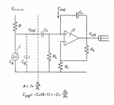
Yes, I already mentioned that with respect to the possible change to the 2SK222. The idea is with a simple impedance converter the input capacitance divides the signal and gives no gain so now you need an even better preamp. So in my case I have a 55pF capsule and a 5pF feedback and get 22nV noise out for a 1nV FET even with 50pF parasitic. So after the output you are working 22nV vs 1nV against the next stage. In the first case there are many easy choices that will no further degrade SNR.
The benefit is admittedly indirect.
-Peace
- Status
- Not open for further replies.
- Home
- Amplifiers
- Solid State
- John Curl's Blowtorch preamplifier