>are there non ferrous things that absorb RF
>other than a coil of wire acting like an inductor??
http://www.hobby-hour.com/electronics/metal_detectors.php
>other than a coil of wire acting like an inductor??
http://www.hobby-hour.com/electronics/metal_detectors.php
Bob Cordell said:First, the fact that this was on the AC side of the power supply, which is not directly in the signal path. This then raises the question of whether what the ferrite was doing to the sound was as a result of it somehow distortiong the AC...
Bob, this isn't going to make much sense, but it's the truth. So-called "tweaks" (eg, a ferrite RFI filter) tend to have the same sonic impact no matter where you use it.
In other words, let's say you buy one of the original PS Audio power "regenerators". I'm going to ignore a lot of the whys and wherefores and mostly just concentrate on the results. First of all, the original ones had an oscillator driving a big class A/B audio amp driving a step-up transformer to provide AC power that was supposed to be purer than what came from the wall.
Now, if you hooked one of those up in your system and started playing around with it, you would find two things very quickly:
1) They tended to make the components they powered have a sonic flavor of a high-feedback solid-state circuit. In other words, if you plugged in a Conrad-Johnson tube preamp into it, the resulting sound would have more bass "slam", there would be more apparent resolution of detail, and things might tend to sound a little bit brighter and more forward. In other words, almost as if you had added a high-feedback solid-state component into the signal chain.
In a way this makes sense because you *did* add a high-feedback solid-state amp to your system. But on the other hand, how did the sonic signature of the high-feedback solid-state amp get through the power supply of the tube preamp and alter the sonic effect of that preamp? There is no obvious acceptable explanation -- at least none that I'm aware of.
2) It didn't matter what you plugged into it, it would tend to have the same sonic effect. Again, this almost makes sense. If you buy off on part (1), then it would make sense that it might have the same type of sonic effect on a tube preamp that it would on a tube CD player.
But on the other hand, it would make the exact same kind of sonic difference if you plugged a turntable with a 120 VAC synchronous motor into it. Again, I have no plausible explanation for how the sonic characteristic of the power regenerator could possibly affect the rotation of the motor such that a specific sonic character was induced into LP playback. But that is exactly what happens.
And it's the same with ferrites. It doesn't really matter if you put them on the AC side of the power supply, the DC side of the power supply, or in the signal path itself -- they are still going to create a similar sonic imprint on your system. And again, I have no plausible explanations whatsoever. Nonetheless, I have performed these tests enough times to be confident in the results.
And for what it's worth, I do my listening tests blind most of the time. For example, Vishay recently shut down the Roederstein resistor factory (actually called Draloric). Those resistors are now made in the Beyschlag factory. According to Vishay, they are absolutely identical and completely interchangeable. When the change was announced we got some samples from each factory to see how much the sound changed (if at all). I had one of our tech make two sets of fixed attenuators that went between the CD player and the power amp, replacing the preamp. The attenuator plugged directly into the input of the power amp so there wasn't any issue with driving the cables.
They would swap the attenuators back and forth and I would listen to see if there were any differences, and if so, which ones sounded better. It was funny because just listening to the first presentation I could tell that those were the Draloric resistors that we had been using for 15 years. There wasn't any need to even try to hide the identity of the other ones, as I could tell which was which without even comparing them. It would be kind of like kissing a woman while blindfolded. You wouldn't have to go back and forth to tell which one was your wife -- you could identify her immediately without having to compare kisses with the other woman.
Anyway the point I am trying to make is that I conduct my listening tests very carefully. I make sure that I am familiar with the system and the program material. I only change one variable at a time. I usually do the test blind. And usually there is at least one other person present. After each listening session I ask them what they heard before I make any comments. It is rare for us to disagree on what we heard. On those occasions where we disagree, we spend more time listening until we reach an agreement on what we are hearing. (Normally the best way to do this is to keep trying different source material until we find a song that highlights the differences caused by the changes to the circuitry. Then it becomes obvious to everyone in the room as to what is happening sonically.)
Anyway, it's a long-winded way of saying that I don't have any good answers to your questions, despite the fact that they are good questions.
Terry Demol said:Small air core L // with copper endcap R?
Not what we do, but not a bad idea. A version of this for digital and/or RF work is explained in Howard Johnson's second book, "High Speed Signal Propagation: Advanced Black Magic".
JFET source resistance cap comp al la Lineup
.
I like to get a G.Kleinschmidt, Scott Wurcer, John Curl or Bob Cordell comment on the following fenomena.
Complementary JFET input Stage.
I have found a trick to deal with it.
I call it Lineup JFET Cap compensation 😉
I have found out .. on my own.
Because I do not read technical literature about transistors.
2SK170 + 2SJ74 are almost complementary.
At least there is a 'sweet spot' where they cancel even harmonics.
I have found this spot is Not at same VGS for the N-FET and P-FET.
More closer to when the N and P works at same current I-DS.
The practical choice of making Practically this means making both source resistors equal value.
And run this complementary at same current level.
This also means, that using a potentiometer as divider between such pair, in a 'wrong way',
can create even order distortion of considerable magnitude.
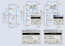
Three circuits to demonstrate this fenomena.
And the one to the right, is one solution I use, to compensate and make them N-JFET and P-JFET work in
Complementary Harmony.
I post some harmonics difference in next post.
Regars Lineup
.
I like to get a G.Kleinschmidt, Scott Wurcer, John Curl or Bob Cordell comment on the following fenomena.
Complementary JFET input Stage.
I have found a trick to deal with it.
I call it Lineup JFET Cap compensation 😉
I have found out .. on my own.
Because I do not read technical literature about transistors.
2SK170 + 2SJ74 are almost complementary.
At least there is a 'sweet spot' where they cancel even harmonics.
I have found this spot is Not at same VGS for the N-FET and P-FET.
More closer to when the N and P works at same current I-DS.
The practical choice of making Practically this means making both source resistors equal value.
And run this complementary at same current level.
This also means, that using a potentiometer as divider between such pair, in a 'wrong way',
can create even order distortion of considerable magnitude.
Three circuits to demonstrate this fenomena.
And the one to the right, is one solution I use, to compensate and make them N-JFET and P-JFET work in
Complementary Harmony.
I post some harmonics difference in next post.
Regars Lineup
Attachments
😎
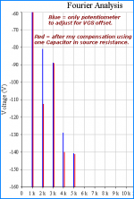
Here is my comparing FFT analys.
Before and after one such my Capacitor Compensation. As I call it.
In this case was a difference of -32 dB for 2nd order harmonics!.
But quite often there are improvements at like -10 to -20dB level.
These are very high magnitudes, People!
My CapComp Trick.
This allows for ZERO DC-offset adjustment and still cancels out even order distortion.
Making the 2SK170 / 2SJ74 Complementary input/pair work at as low distortion as possible.
A hookup is, that you probably need some distortion measurement device.
Unless there are some mathematical way, by just measuring VGS or whatever.
😎 ESP has a project to build a THD harmonics analyser.
😎 Bob Cordell has the definitive THD analyzer building project at his website.
CORDELL AUDIO - Build a High Performance THD Analyzer
This three-part construction article described a high performance THD analyzer that an individual could build affordably. THD analyzers are traditionally expensive and out of reach for the average DIY audio enthusiast, yet they are indispensable in designing audio power amplifiers and other equipment. The unit described in this construction article is every bit as sensitive as the best commercial THD analyzers, with a THD+N measurement floor below 0.001 percent out to 20 kHz.
http://www.cordellaudio.com/papers/build_a_thd_analyzer.shtml
Lineup
Attachments
I think the brain also has something to do with what we perceive as well.
You might not be able to measure the cause of the difference (because, maybe there IS NO DIFFERENCE), but your brain is an entirely different matter. If it is expecting a difference, that is what you will hear.
😕
You might not be able to measure the cause of the difference (because, maybe there IS NO DIFFERENCE), but your brain is an entirely different matter. If it is expecting a difference, that is what you will hear.
😕
Re: JFET source resistance cap comp al la Lineup
Unless I am mistaken,
I think the same issue is adressed by Wurcer in this post in the topic:
Ultrasimple mm/mc RIAA preamp 2
http://www.diyaudio.com/forums/showthread.php?postid=1299352#post1299352
-----------------------------------------------------------------------
Originally posted by scott wurcer :
BTW you should be able to build a small adjustable -Vgs biaser
with a single 1.5V cell and some BIG resistors.
You could then adjust each FET for equal Id, obviating the selection/matching requrements.
A 1 MOhm pot between ground and -1.5V and a 10 Meg resistor to the gate on each should do.
The same geometry FET has
- about the same gm
- at a given Id
- with very little sensitivity to Idss.
-----------------------------------------------------------------------
Regars, Lineup - Audio Research Labs
.
I like to get a G.Kleinschmidt, Scott Wurcer, John Curl or Bob Cordell comment on the following fenomena.
Complementary JFET input Stage.
I have found a trick to deal with it.
I call it Lineup JFET Cap compensation 😉
I have found out .. on my own.
Because I do not read technical literature about transistors.
2SK170 + 2SJ74 are almost complementary.
At least there is a 'sweet spot' where they cancel even harmonics.
.
Unless I am mistaken,
I think the same issue is adressed by Wurcer in this post in the topic:
Ultrasimple mm/mc RIAA preamp 2
http://www.diyaudio.com/forums/showthread.php?postid=1299352#post1299352
-----------------------------------------------------------------------
Originally posted by scott wurcer :
BTW you should be able to build a small adjustable -Vgs biaser
with a single 1.5V cell and some BIG resistors.
You could then adjust each FET for equal Id, obviating the selection/matching requrements.
A 1 MOhm pot between ground and -1.5V and a 10 Meg resistor to the gate on each should do.
The same geometry FET has
- about the same gm
- at a given Id
- with very little sensitivity to Idss.
-----------------------------------------------------------------------
Regars, Lineup - Audio Research Labs
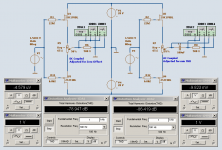
Here's a final image
to illustrate the case I am enquiering about.
Regarding Complementary JFET stage adjustment.
🙂
The difference is that The AC-Coupled version
runs at equal current, for both N-JFET and P-JFET.
This gives the lowest thd distortion level.
Reduces even order harmonics considerably.
to illustrate the case I am enquiering about.
Regarding Complementary JFET stage adjustment.
🙂
The difference is that The AC-Coupled version
runs at equal current, for both N-JFET and P-JFET.
This gives the lowest thd distortion level.
Reduces even order harmonics considerably.
Attachments
syn08 said:
What exactly does "high frequency" mean in this context? 1MHz? 10MHz? 100MHz?
High frequency in the radio spectrum is 3 MHz to 30 MHz. High frequency as far as parasitic cable impedance affecting measurements for short (<1/10 lambda) cables begins at about 10 MHz in our lab.
Best, Chuck Hansen
Terry Demol said:
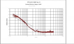
What sort of spectrum did it transmit?
Here is the spectrum of the "buzzing relay" induced conducted emissions on the power line as measured by an RF current probe and EMI receiver, measurement band 150 kHz to 30 HMz. Vertical axis is dB above 1 uA.
Best, Chuck Hansen
Attachments
hitsware said:>are there non ferrous things that absorb RF
>other than a coil of wire acting like an inductor??
http://www.hobby-hour.com/electronics/metal_detectors.php
Sorry what? That's link's a metal detector?
lineup:
i am not one of the experts, but a question for you if i may:
did you build real prototypes and test those? i would be concerned that you are tweaking for spice models differences otherwise ...
mlloyd1
i am not one of the experts, but a question for you if i may:
did you build real prototypes and test those? i would be concerned that you are tweaking for spice models differences otherwise ...
mlloyd1
lineup said:Here's a final image
to illustrate the case I am enquiering about.
Regarding Complementary JFET stage adjustment.
🙂
The difference is that The AC-Coupled version
runs at equal current, for both N-JFET and P-JFET.
This gives the lowest thd distortion level.
Reduces even order harmonics considerably.
Several years ago, I wondered about the real sonic effects of the common mode return connection that is made through the AC power mains. Eventually, I was able to measure a low level common mode signal that more or less correlated to the system audio on the AC mains as well as on the power connection. I used a borrowed Fluke battery powered oscilloscope and a home made current "probe" on the cables.
Various ferrites had an effect on the measured common mode signal, but they sounded ugly after a while. I then tried a common mode choke wound on a toroidal core taken from a power transformer. I figured that the effects of this kind of core would be similar to what the regular power transformer wrought, without the ferrite effects. Only the hot and neutral wires were wound on this core, with the safety ground connected separately; I didn't want to add whatever signals carried on the hot and neutral to be transferred to the ground as well. To make the story short, the common mode signal dropped and the system performance improved somewhat.
From my day job experience, I can say that applying the right type of ferrite is not as easy as choosing a resistor. That's not even taking into account the effects described by Professor Hansen. (We don't do audio products at work...)
Here's a source of information on this:
http://www.hottconsultants.com/index.html
Re: Re: Re: FET/BJT
Closed loop, but this is a very speculative design with a high chance of failure.
PHEONIX said:
Hello Scott,
May I ask is this an open loop design or one with feedback.
Regards
Arthur
Closed loop, but this is a very speculative design with a high chance of failure.
bear said:
Sorry what? That's link's a metal detector?
Metal detectors sense metals other than ferrous.
I was relating to the possibility that say, gold beads
could have the positive attributes of ferrite beads
without the problems cited ?
Charles Hansen said:
Bob, this isn't going to make much sense, but it's the truth. So-called "tweaks" (eg, a ferrite RFI filter) tend to have the same sonic impact no matter where you use it.
In other words, let's say you buy one of the original PS Audio power "regenerators". I'm going to ignore a lot of the whys and wherefores and mostly just concentrate on the results. First of all, the original ones had an oscillator driving a big class A/B audio amp driving a step-up transformer to provide AC power that was supposed to be purer than what came from the wall.
Now, if you hooked one of those up in your system and started playing around with it, you would find two things very quickly:
1) They tended to make the components they powered have a sonic flavor of a high-feedback solid-state circuit. In other words, if you plugged in a Conrad-Johnson tube preamp into it, the resulting sound would have more bass "slam", there would be more apparent resolution of detail, and things might tend to sound a little bit brighter and more forward. In other words, almost as if you had added a high-feedback solid-state component into the signal chain.
In a way this makes sense because you *did* add a high-feedback solid-state amp to your system. But on the other hand, how did the sonic signature of the high-feedback solid-state amp get through the power supply of the tube preamp and alter the sonic effect of that preamp? There is no obvious acceptable explanation -- at least none that I'm aware of.
2) It didn't matter what you plugged into it, it would tend to have the same sonic effect. Again, this almost makes sense. If you buy off on part (1), then it would make sense that it might have the same type of sonic effect on a tube preamp that it would on a tube CD player.
But on the other hand, it would make the exact same kind of sonic difference if you plugged a turntable with a 120 VAC synchronous motor into it. Again, I have no plausible explanation for how the sonic characteristic of the power regenerator could possibly affect the rotation of the motor such that a specific sonic character was induced into LP playback. But that is exactly what happens.
And it's the same with ferrites. It doesn't really matter if you put them on the AC side of the power supply, the DC side of the power supply, or in the signal path itself -- they are still going to create a similar sonic imprint on your system. And again, I have no plausible explanations whatsoever. Nonetheless, I have performed these tests enough times to be confident in the results.
And for what it's worth, I do my listening tests blind most of the time. For example, Vishay recently shut down the Roederstein resistor factory (actually called Draloric). Those resistors are now made in the Beyschlag factory. According to Vishay, they are absolutely identical and completely interchangeable. When the change was announced we got some samples from each factory to see how much the sound changed (if at all). I had one of our tech make two sets of fixed attenuators that went between the CD player and the power amp, replacing the preamp. The attenuator plugged directly into the input of the power amp so there wasn't any issue with driving the cables.
They would swap the attenuators back and forth and I would listen to see if there were any differences, and if so, which ones sounded better. It was funny because just listening to the first presentation I could tell that those were the Draloric resistors that we had been using for 15 years. There wasn't any need to even try to hide the identity of the other ones, as I could tell which was which without even comparing them. It would be kind of like kissing a woman while blindfolded. You wouldn't have to go back and forth to tell which one was your wife -- you could identify her immediately without having to compare kisses with the other woman.
Anyway the point I am trying to make is that I conduct my listening tests very carefully. I make sure that I am familiar with the system and the program material. I only change one variable at a time. I usually do the test blind. And usually there is at least one other person present. After each listening session I ask them what they heard before I make any comments. It is rare for us to disagree on what we heard. On those occasions where we disagree, we spend more time listening until we reach an agreement on what we are hearing. (Normally the best way to do this is to keep trying different source material until we find a song that highlights the differences caused by the changes to the circuitry. Then it becomes obvious to everyone in the room as to what is happening sonically.)
Anyway, it's a long-winded way of saying that I don't have any good answers to your questions, despite the fact that they are good questions.
Hi Charles,
Thanks again for another thoughtful, detailed, and candid answer.
I appreciate that you are willing to say that you just don't understand why. We'll cross it off to the "X Factor".
Thanks also for describing your listening test approach, and I'm happy to see that it does include some blind testing.
Thanks,
Bob
They tended to make the components they powered have a sonic flavor of a high-feedback solid-state circuit. In other words, if you plugged in a Conrad-Johnson tube preamp into it, the resulting sound would have more bass "slam", there would be more apparent resolution of detail, and things might tend to sound a little bit brighter and more forward. In other words, almost as if you had added a high-feedback solid-state component into the signal chain.
That is very interesting. Gordon Holt always described the sound of tube gear as being brighter and more forward than solid state gear. Have you solid state guys been making your stuff brighter over the years?
AC side?Bob Cordell said:
Hi Charles,
Thanks for this thoughtful answer. There is a lot of interesting stuff to ponder here.
Two things in particular jump out, if I read you right:
First, the fact that this was on the AC side of the power supply, which is not directly in the signal path. This then raises the question of whether what the ferrite was doing to the sound was as a result of it somehow distortiong the AC, failing to filter something coming in from the outside (or modifying in some way that garbage), or, finally, whether the ferrite was causing some kind of magnetic field of junk to be coupled into the signal path of the amplifier.
Cheers,
Bob
This shows why filtering after the rectifier is important . -isolation.
everything, back to the generator and its motor are in the circuit, in parallel.
Christer said:This RFI discussion has been very interesting an goes much deeper than any previous one I remember.
I am very bad att HF theory, but Bobs suggestion of a filter immediately att the input connector sounds (at least intuitively) wise. If I understand him right, he suggest basically a voltage divider type of RC link. Another possibility would be a Zobel filter, ie. a series RC link between signal and ground. In my limited understanding of HF theory those two variants would seem to serve the same purpose for HF, ie. an HF signal would see 50 Ohms to ground in both cases. Is that a correct understanding?
So far inputs has been discussed, but the output of an amp is also a potential RFI path into the amp. I remeber Rod Elliot writing many years ago that he suspected that might be a problem since RFI that sneaks in that way will have a fairly direct path to the input stage through the feedback network. His suggestion was to add a Zobel at the output connectors. For line level amps, Bobs solution would often be OK also at the output, if mirroring it, viewing the output as an input (for HF). Any thoughts on output RFI filters?
Sorry for quoting myself, but I just wonder if this got lost in the noise in the thread or if everyone finds it so trivial and boring that isn't interesting?
Anyhow, Sigurd has, perhaps unknowingly, commented on some of it in another thread recently and seems to agree that an output Zobel filter is a good idea.
http://www.diyaudio.com/forums/showthread.php?postid=1551357#post1551357
Charles Hansen said:
Bob, this isn't going to make much sense, but it's the truth. So-called "tweaks" (eg, a ferrite RFI filter) tend to have the same sonic impact no matter where you use it.
In other words, let's say you buy one of the original PS Audio power "regenerators". I'm going to ignore a lot of the whys and wherefores and mostly just concentrate on the results. First of all, the original ones had an oscillator driving a big class A/B audio amp driving a step-up transformer to provide AC power that was supposed to be purer than what came from the wall.
Now, if you hooked one of those up in your system and started playing around with it, you would find two things very quickly:
1) They tended to make the components they powered have a sonic flavor of a high-feedback solid-state circuit. In other words, if you plugged in a Conrad-Johnson tube preamp into it, the resulting sound would have more bass "slam", there would be more apparent resolution of detail, and things might tend to sound a little bit brighter and more forward. In other words, almost as if you had added a high-feedback solid-state component into the signal chain.
In a way this makes sense because you *did* add a high-feedback solid-state amp to your system. But on the other hand, how did the sonic signature of the high-feedback solid-state amp get through the power supply of the tube preamp and alter the sonic effect of that preamp? There is no obvious acceptable explanation -- at least none that I'm aware of.
2) It didn't matter what you plugged into it, it would tend to have the same sonic effect. Again, this almost makes sense. If you buy off on part (1), then it would make sense that it might have the same type of sonic effect on a tube preamp that it would on a tube CD player.
But on the other hand, it would make the exact same kind of sonic difference if you plugged a turntable with a 120 VAC synchronous motor into it. Again, I have no plausible explanation for how the sonic characteristic of the power regenerator could possibly affect the rotation of the motor such that a specific sonic character was induced into LP playback. But that is exactly what happens.
And it's the same with ferrites. It doesn't really matter if you put them on the AC side of the power supply, the DC side of the power supply, or in the signal path itself -- they are still going to create a similar sonic imprint on your system. And again, I have no plausible explanations whatsoever. Nonetheless, I have performed these tests enough times to be confident in the results.
And for what it's worth, I do my listening tests blind most of the time. For example, Vishay recently shut down the Roederstein resistor factory (actually called Draloric). Those resistors are now made in the Beyschlag factory. According to Vishay, they are absolutely identical and completely interchangeable. When the change was announced we got some samples from each factory to see how much the sound changed (if at all). I had one of our tech make two sets of fixed attenuators that went between the CD player and the power amp, replacing the preamp. The attenuator plugged directly into the input of the power amp so there wasn't any issue with driving the cables.
They would swap the attenuators back and forth and I would listen to see if there were any differences, and if so, which ones sounded better. It was funny because just listening to the first presentation I could tell that those were the Draloric resistors that we had been using for 15 years. There wasn't any need to even try to hide the identity of the other ones, as I could tell which was which without even comparing them. It would be kind of like kissing a woman while blindfolded. You wouldn't have to go back and forth to tell which one was your wife -- you could identify her immediately without having to compare kisses with the other woman.
Anyway the point I am trying to make is that I conduct my listening tests very carefully. I make sure that I am familiar with the system and the program material. I only change one variable at a time. I usually do the test blind. And usually there is at least one other person present. After each listening session I ask them what they heard before I make any comments. It is rare for us to disagree on what we heard. On those occasions where we disagree, we spend more time listening until we reach an agreement on what we are hearing. (Normally the best way to do this is to keep trying different source material until we find a song that highlights the differences caused by the changes to the circuitry. Then it becomes obvious to everyone in the room as to what is happening sonically.)
Anyway, it's a long-winded way of saying that I don't have any good answers to your questions, despite the fact that they are good questions.
Hi Charles,
It is interesting to hear about your methods, and I was wondering if you've ever tried using a program such as this to determine how the signal was (or not) changing:
http://www.libinst.com/Audio DiffMaker.htm
- Status
- Not open for further replies.
- Home
- Amplifiers
- Solid State
- John Curl's Blowtorch preamplifier