john curl said:You are incorrect, Glen. The simulations prove it.
John, that statement implies that you've changed your point of view with respect to simulation. Your post that begins the SPICE thread says this:
Spice emulations? I don't need no stinking Spice emulations! (think bandito icon)
Count me in with Bob Pease on this one. ;-)
I just measure them in REAL-TIME with capacitors and a square wave generator, as I learned to do at my mentor's side, 40 years ago.
Would you be willing to post to the SPICE thread that you've changed your position on this? Your initial post to that thread sets its tone, and I believe that tone is more negative than your current view.
john curl said:Is that a professional reply to my challenge?
What challenge? It sounds as if you misread what I said. I’m talking about complete front-end designs here, not just the input long tail pairs which are only a part. I’ve done plenty of sims that confirm that a fully symmetrical front end can be made just as fast and just as linear as any asymmetrical design.
And no, I don’t like jfets for differential long tail pair inputs unless a CMCL (see Edmonds stuff) is used to steer the VAS biasing, allowing high impedance LTP loads. Their gm is just too low for adequate (in my eyes) gain and linearity otherwise.
I personally don't care what you like or don't like. I use complementary fet input stages and I have used them for the last 35 years or so. You can do what you like, but it is unprofessional to criticize the work of another professional without evidence or proof. I suspect that my circuits will easily compete with yours, the only real difference will be the final application and my circuits might be less complex, yet more sophisticated.
For example, if you talk about high power, I made a 2000W power amp back in 1969 with airblown heatsinks, but it would be impractical for audio. I now make a fully rated 800W into 4 ohm amplifier that is for sale across the world. I could easily turn it into a 2500W amplifier with a bridge design and fans. No big problem, and it would have a slew rate greater than 100V/us easily. I have been doing this for decades. The only thing that really changes with time is that the output devices get better and stronger, and I use the best that we can find.
What brings you or anyone to impugn my efforts? Why? Are there not other threads where you can show your competence?
Andy C, you are misinformed. I have used circuit emulation for the last 42 years. Yes, I even modeled the germanium 2n1305, myself with a semiconductor curve tracer in 1966. We found probems with emulation, even then, than made me a little shy of using ANY circuit analysis program. I am old enough to have finished college without needing a computer, or even a calculator to do the coursework. This is both a blessing and a curse, but I can do more without a computer than many can do with a computer, because of this.
In 1970 I took several courses in linear engineering from 'the father of SPICE', Don Pederson Look him up, if you don't believe me. He was one of the best professor's that I ever studied under, but his class notes were mostly hand derived, not computer simulated, and I have them still in my possession. In those days, computer derived distortion was a rough approximation, and the models were VERY complex. I tried and failed in 1973 to get a good SPICE simulation on the UCB computer of one of my fet circuits, so I let it go.
Today, 35 years later, perhaps things have caught up, and certain individuals who possess very high talent and standards might be able to emulate circuits pretty well. That is why I trust PMA to do generic comparisons on his SPICE emulation. I can't do that well as yet, so I just do it the old fashioned way. I build it, and then test it. Is this so difficult for you to understand?
My comment: 'I don't need no stinkin' SPICE' still stands, I don't need it, but it can be useful on occasion. Doesn't that make sense to you?
john curl said:I personally don't care what you like or don't like. I use complementary fet input stages and I have used them for the last 35 years or so. You can do what you like, but it is unprofessional to criticize the work of another professional without evidence or proof. I suspect that my circuits will easily compete with yours, the only real difference will be the final application and my circuits might be less complex, yet more sophisticated.
For example, if you talk about high power, I made a 2000W power amp back in 1969 with airblown heatsinks, but it would be impractical for audio. I now make a fully rated 800W into 4 ohm amplifier that is for sale across the world. I could easily turn it into a 2500W amplifier with a bridge design and fans. No big problem, and it would have a slew rate greater than 100V/us easily. I have been doing this for decades. The only thing that really changes with time is that the output devices get better and stronger, and I use the best that we can find.
What brings you or anyone to impugn my efforts? Why? Are there not other threads where you can show your competence?
What on earth are you going on about? I prefer not to use dual jfets in preference to dual BJT's for a specific application (LTP's without a high impedance drain load) and I gave the reason why. Why is that so offensive?
john curl said:
I think the example would be more clear if and when you can go back to fets as an input. There, the differences should be more pronounced, expecially with high drive.
Hopefuly I will, later.
Just one point to remind - the simulations on JFET circuit resulted in simulations of balanced input / balanced output topology.
The simulations of my BJT preamp, and the measurement shown as well, is performed on a single-ended input / single ended output circuit, though complementary-differential. It makes difference, especially in the spectral contents.
john curl said:You are incorrect, Glen. The simulations prove it. It should be obvious from inspection for an experienced engineer, when making the comparison between a single differential pair and a complementary differential pair. Everyone else will just have to accept it, or prove us wrong.
Sorry John,
Glen is NOT incorrect. If you read his post more carefully, you will see he is talking about long tailed pairs. Regarding the input (and, for the moment, neglecting the consequences for the rest of the circuit), adding a complementary LTP is pointless, except that two times more output current is available and a bit less noise. Using D. Self's words: "you cannot balance a stage that is already balanced".
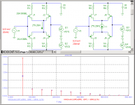
BUT.... looking at Pavel's experiments, I suppose you are talking about a different kind of input stage, something like J1...J4 in the figure below. Opposed to the second input stage (J5...J8) the first one does NOT contain LTPs, which makes a distinct difference in distortion. In this respect you are right.
I've repeated Pavel's simulations in a slightly different (and more meaningful!) way, that is, keeping the standing drain currents exactly the same (and of course the output currents too, 2mApk-pk).
Now we see that 3rd harmonic is halved compared to the true complementary LTP stage. BTW, In Pavel's simulating, the drain current of the latter was only half as large. Therefore, the 3rd harmonic was much higher.
I hope I've removed most of the confusion.
Regards,
Edmond.
Attachments
Hi Edmond,
you've lost me.
Why does the first (J1 to J4) not contain LTPs?
But the second (J5 to J6), which has the same connections, contains two LTPs?
you've lost me.
Why does the first (J1 to J4) not contain LTPs?
But the second (J5 to J6), which has the same connections, contains two LTPs?
AndrewT said:Hi Edmond,
you've lost me.
Why does the first (J1 to J4) not contain LTPs?
But the second (J5 to J6), which has the same connections, contains two LTPs?
Hi Andrew,
Simply, because the sources are not connected to a constant current source. IOW, they are pairs without tail. 🙂
Cheers,
Edmond.
Hi,
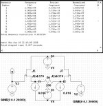
are you saying that the 2*9.28mA in the first diagram is not constant?
whereas the same current shown as I1 IS HELD CONSTANT.
are you saying that the 2*9.28mA in the first diagram is not constant?
whereas the same current shown as I1 IS HELD CONSTANT.
A differential gives an opposite phase signal only because the sum of currents through both transistors is held constant (by a constant current source).
In the first schematic the CCS is missing, so no interaction between both halves.
Have fun, Hannes
EDIT: I haven't seen your reply: there's no mechanism in the 1st schematic which would force constant current.
In the first schematic the CCS is missing, so no interaction between both halves.
Have fun, Hannes
EDIT: I haven't seen your reply: there's no mechanism in the 1st schematic which would force constant current.
Edmond Stuart said:Regarding the input (and, for the moment, neglecting the consequences for the rest of the circuit), adding a complementary LTP is pointless, except that two times more output current is available and a bit less noise. Using D. Self's words: "you cannot balance a stage that is already balanced".
Hi Edmond,
IMHO, in this case D. Self is not quite right (and he did miss the same problem before). There is one more point which can not be neglected - the unlinearity of the input impedance for BJT input due to the base currents of LTP transistors. In a complementary LTP input not only DC component of the input current could be cancelled to a good degree but the unlinearities of the input impedance may be reduced.
Cheers
Alex
AndrewT said:Hi,
are you saying that the 2*9.28mA in the first diagram is not constant?
whereas the same current shown as I1 IS HELD CONSTANT.
Hi Andrew,
Precisely. If this current was constant, then the distortion figures would be equal, which is not the case.
Cheers,
Edmond.
x-pro said:Hi Edmond,
IMHO, in this case D. Self is not quite right (and he did miss the same problem before). There is one more point which can not be neglected - the unlinearity of the input impedance for BJT input due to the base currents of LTP transistors. In a complementary LTP input not only DC component of the input current could be cancelled to a good degree
Agreed, but as you said, to a good (or some) degree.
but the unlinearities of the input impedance may be reduced.
Cheers
Alex
Hmm.... but to what extent and why? The nonlinear behavior of the PNPs may be quite different from the NPNs.
Furthermore, normally the input is tied to a low impedances source, so, how much we would benefit from this kind of cancellation.
BTW, please don't misunderstand me, I'm also a fan of fully complementary designs.
Cheers,
Edmond.
WRT complementary jfet versus same sex dif pair, I think we are talking
about linearity of the -current- generated.
This is after all the Blowtorch thread, the discussion is, or should be
hinging around design elements of zero or low FB topologies.
In this case, we are interested in an accurate -current- generated at
the IP pair through a degeneration resistor. This will be used later
to get whatever voltage gain we require.
As such, a complementary, high gm, jfet dif pair will generate way
less distortion than straight n or p channel dif pair.
Ref same sex dif pair below.
cheers
T
Attachments
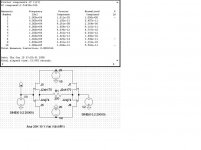
Yes, as already shown in:
http://web.telecom.cz/macura/diyaudio/jfetdist.htm
but for some reason guys did not want to click to my "www" button below the post.
http://web.telecom.cz/macura/diyaudio/jfetdist.htm
but for some reason guys did not want to click to my "www" button below the post.
Both examples have same 14mA current,
the compl pair has nearly 8 x lower distortion.
When the AC current swing to idle current ratio, or the
R load to 1/gm ratio is pushed harder, the complementary
pair pulls even further ahead. An example of this would be
hiigh gain mic pre or MC IP stage.
I would say John knows very much what he is talking about.
cheers
Terry
Now, we are at stage 2 of an idea. 'It exists, but it is not important.' Thanks Terry and PMA.
I disagree with the assertions.
You need to look at the final result.
Bottom line is Cordell's amp produced a superb set of measured results that set the benchmarl for 20 years. I'd venture that PGP sets th e latest breakthrough performance levels.
If we ar e going to be even handed in this discussion, lets also hammer (or is it nail?) JC for continually referencing his 1960's work.
- Status
- Not open for further replies.
- Home
- Amplifiers
- Solid State
- John Curl's Blowtorch preamplifier