Edmond Stuart said:
bipolars will have even harmonics ...... in a diff pair
No! Any (perfectly) symmetrical circuit will only produce odd harmonics.
edit: Oops, that too is not true. I mean: cannot produce even harmonics.
Yes, I stand corrected. Perfect symmetrical diff circuits always cancel the even harmonics. Their equation is always an odd function.
Nelson Pass said:Thanks. Always comforting to see measurement confirmed by simulation. 😉
Me too 😉 . At least there is a lesser probability that both were wrong. The Vds was a good point.
It is a 2nd time you gave me a good hint 😉 .
john curl said:PS I use your AD797 op amps in the front end of my Sound Technology, as well. They work great for instrumentation.
Same here, I put them in my HP-339A, they do work great. I agree with the adverse cost factor for volume production, very pricey.
Best, Chuck Hansen
andy_c said:
Hi Pavel,
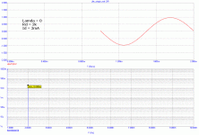
If you set LAMBDA=0 in the JFET model, this should also force pure square law behavior even as Vds varies - as long as Vds does not get so small that the FET goes into the triode region. This might be convenient for some simulations.
Thanks, Andy. I confirm this. With Lambda=0 there is only 2nd harmonic even in case that there is a drain resistor load and Vds is not constant, very good.
Attachments
Well, for lambda=0 (channel-length modulation) the transfer function is true square. I assume they are not created. You can find something at very very unreasonable low levels, like 1E-11, just for the reason of precision of the FFT computation.
john curl said:Distortion harmonics, silly!
I did not get it. There is always a limit of computation precision, and FFT result also depends on window, ratio of periods to window legth etc. etc. Real measurement as well.
The harmonics, except for 2nd, are less than -140dB, with respect to 1st. Can you hear them or measure them?
Terse posts are even more silly.john curl said:Distortion harmonics, silly!
PMA and Edmond, please lighten up. I am only trying to stay on target. Please read what I have to say, and try to understand my meaning, first, before asking redundant questions. It only slows and confuses the process.
Also, everyone, please forgive my incompleteness on occasion. I am typing on the fly, with only a cursory check on my spelling, etc. I am not teaching a course.
Also, everyone, please forgive my incompleteness on occasion. I am typing on the fly, with only a cursory check on my spelling, etc. I am not teaching a course.
be happy
OK John, but why you insist to persuade us to give/develop an exact algebraic expression for the 3rd harmonic, as it is soooo obvious that they will show up in any symmetrical circuit. Why aren't you happy with the outcome of a simple simulation? It does tell all you need to know (i.e. fets are better than bjts, if one can get them ).
).
Cheers, Edmond.
john curl said:PMA and Edmond, please lighten up. I am only trying to stay on target. Please read what I have to say, and try to understand my meaning, first, before asking redundant questions. It only slows and confuses the process.
Also, everyone, please forgive my incompleteness on occasion. I am typing on the fly, with only a cursory check on my spelling, etc. I am not teaching a course.
OK John, but why you insist to persuade us to give/develop an exact algebraic expression for the 3rd harmonic, as it is soooo obvious that they will show up in any symmetrical circuit. Why aren't you happy with the outcome of a simple simulation? It does tell all you need to know (i.e. fets are better than bjts, if one can get them
 ).
).Cheers, Edmond.
Edmond, this is the Blowtorch thread. If I want to share the subtle qualities of fet circuit design with others, that is my choice. I already know fet circuit design. I also have a former associate looking into his class notes and he should get back to be shortly.
Onvinyl said:Hi Pavel,
would you mind to try lower values, say between 2.2r - 22r?
Rüdiger
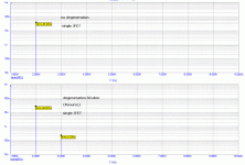
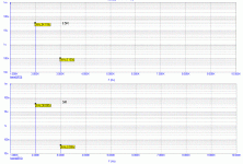
No problem (I hope John would digest it). For single device, 5R and 15R. Also remember that distortion absolute value will be device dependent:
P.S.: for true diffpair (balanced in, balanced out) distortion spectrum does not change with degeneration.
Attachments
john curl said:Do they 'cancel' or convert?
John,
You asked for equations, now you are asking for a phenomenologic view of the distortions in a differential stage. Until your associate comes back with something, probably in a language that you are more comfortable with, here's an gedanken experiment on why a perfectly symmetric differential stage cannot have second harmonic distortions.
Imagine an perfectly symmetrical differential stage with no degeneration. Do not make any assumption about the building devices, they can be bipolars, FETs, MOSFETs, tubes, whatever you like. The only thing you need to know is the dependency of the device current i to the device input voltage u, and let's assume this dependency is an arbitrary function i=f(u). You may think of “f” as a generic, non-linear, device transconductance.
Let's define the current throungh the left device as i1=f(u1) and through the right device as i2=f(u2). The differential input voltage equals the devices input voltage difference, so ui=u1-u2.
The output differential signal is proportional to the difference of the currents through the devices, so let's define the differential stage transconductance as G(ui)=(i1-i2)/ui which, following the above equations, will be
G(ui)=(f(u1)-f(u2))/(u1-u2)
How much is G(-ui)? Following the same rationale as above, and considering the stage symmetry, it turns that:
ui=u2-u1
and hence
G(-ui)=(f(u1)-f(u2))/(u2-u1)=-G(ui)
Which makes G an odd function. As discussed before, an odd function may generate only odd harmonics (for similar reasons, a 50% symmetric square wave has only odd harmonics). If you don't feel comfortable with the above math formalism on why G(-ui)=-G(ui) think a differential stage output in the 1st and 3rd quadrants. It is perfectly symmetrical, so if ui generates a response in quadrant 1 then -ui will generate the same response (in module) in quadrant 3.
As you see, we did not make any assumptions about f(u). It doesn’t matter what type of harmonics (even, odd or both) the device (as a single ended stage) has, the differential/balanced stage may have only odd harmonics. If the single ended stage has even harmonics only, then you can think of “converting” the even harmonics to odd harmonics. If the single ended stage has both even and odd harmonics, you may think in terms of “cancelling” the even harmonics. But ultimately, this is not really important. Of course, any asymmetry (like e.g. device matching) will break the above rule, and both even and odd harmonics will appear at the output.
Now, a symmetrical degeneration (or any other symmetrical model enhancement, like deviations from the ideal current JFET square law) doesn't change anything; as long as the symmetry is conserved, you may include the degeneration + lambda + ... = new f'(u). Replace above f(u) with f'(u) and nothing will change from a spectral perspective. Even if the single ended device has both 2nd and 3rd, the differential stage will have only 3rd, 5th, etc...
Why do odd functions have only odd harmonic components? This is not as easy to answer. If you are interested in this detail let me know - but be prepared for a tough(er) math ride.
- Status
- Not open for further replies.
- Home
- Amplifiers
- Solid State
- John Curl's Blowtorch preamplifier


