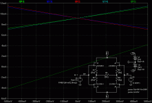
Regular H, values as given here somewhere above: Drain resistors 10R, crossbar resistor 200R.
Gives us ~9mA bias in the sim, and quite linear gm's. With a zero crossbar or the sideways H one could not bias them to the same level and have sufficient degeneration to get a linear gain.
Just like John said, when you need lower resistances to bias than to degenerate, then the regular H is the way to go.
If you need more resistance to bias the FETs than you need for degenerating the gain, then the sideways H seems to fit better.
And the networks cannot be made equivalent (sorry, still no math, though it's not that hard. But a closer look tells us enough without math ;-), unless the crossbar is zero, which is trivial, of course. Other schemes can be thought of, like an "X" overlaid with "| |" or a sideways "| |", or a rectangle... there might be various possibilites, each with distinct properties...
- Klaus
Attachments
Thank you Klaus. There are many different versions as you stated, such as X and square. Even window. You know, double square. 😉
Sorry, Digora, I could not open your attachment, but it should be clear that since this input stage is not necessarily grounded in the source region, it will float to best fit the situation. This can be VERY useful.
. . . In that the output is symmetric, no matter if the input signal is symmetric or not?
And due to the loose coupling of the two halves of the diff stage, there is plenty of headroom before on either side the GS junction is turned on.
Uli

And due to the loose coupling of the two halves of the diff stage, there is plenty of headroom before on either side the GS junction is turned on.
Uli
john curl said:Sorry, Digora, I could not open your attachment
I sent you a pdf copy John, but it looks like only the first page
made it.
For the record, one can also look at the input stage (with the regular H) as a pair of complementary followers with some output resistance, driving differentially into the crossbar resistor. Sort of the current shifter that is used in high speed op-amps (mostly realized with bjt diamond buffers, though).
I have uploaded the PDF of the Hegglun article to:
http://www.filefactory.com/file/8a8626/
Somebody might put it on a real spam/hassle-free server, maybe.
- Klaus
I have uploaded the PDF of the Hegglun article to:
http://www.filefactory.com/file/8a8626/
Somebody might put it on a real spam/hassle-free server, maybe.
- Klaus
KSTR said:Somebody might put it on a real spam/hassle-free server, maybe.
- Klaus [/B]
http://fulloc.free.fr/AUTRE/digora/autre/AmpHegglun.pdf
😉
KSTR said:. . . Gives us ~9mA bias in the sim, and quite linear gm's.
If you need more resistance to bias the FETs than you need for degenerating the gain, then the sideways H seems to fit better. . .
- Klaus
The quirks with SIMs is that nobody owns the average FET with average specs. In fact using 10R source resistors leads to an Id of about 2mA up to about 18mA depending on Idss and gm of the particular REAL device. Somewhere John stated that this Pre is like a study what can be made, cost no object. Luckily I have some dozens of K389BL left, but simply the selection process doesn't give enough equal devices to build more than one stereo Pre without compromising equality. One should hurry buying say 200 K170BLs and another 200 J109BLs to get one amp out of those
😉 😉 😉
Uli
I managed to get about twenty minutes yesterday to whomp up a complementary differential with 2SK170s and 2SJ74s. Played with the vertical H and horizontal H and was glad to see that the vertical H balanced nicely. Didn't have enough time to go much further, but at least my balancing fears were laid to rest.
Grey
Grey
It'll be nice to have another variation in the toolbox. I'll prod at it some more when I get time.
Grey
Grey
Hi Uli,
last week I measured 150 + 150 SJ74BL/Sk170BL and got many matched pairs. What a "matched" is can be agrumented about, but if +-5% is OK, then there is not problem to get matches 🙂
Of course I do not try to get matches within the GR and V grades....
No problems to get a few 100s of SK170/SJ74. Or 1000s.
Sigurd
uli said:
The quirks with SIMs is that nobody owns the average FET with average specs. In fact using 10R source resistors leads to an Id of about 2mA up to about 18mA depending on Idss and gm of the particular REAL device. Somewhere John stated that this Pre is like a study what can be made, cost no object. Luckily I have some dozens of K389BL left, but simply the selection process doesn't give enough equal devices to build more than one stereo Pre without compromising equality. One should hurry buying say 200 K170BLs and another 200 J109BLs to get one amp out of those
😉 😉 😉
Uli
uli said:
The quirks with SIMs is that nobody owns the average FET with average specs. In fact using 10R source resistors leads to an Id of about 2mA up to about 18mA depending on Idss and gm of the particular REAL device.
What I do is to plot the Id - Vgs curve in spice an compare it with the curves in the datasheet. Then I sort IDSS of my real devices, so I can estimate the biasing values. It would be better to trace the actual devices curves, but I hope, I come close.
The IDSS of the 170's spice model is 12.67 mA
Rüdiger
It is also very easy to create new models for JFETs that have
any wanted Idss value.
I have created a few different models for SK170/SJ74 that have different Idss (and Vp) values. I then name them something like:
SK170GR_4m1
SK170BL_6m8
SK170BL_10m
SJ74GR_5m
SJ74V_13m
etc
etc
and use these models when I want to have a more realistic transistor model.
Sigurd
any wanted Idss value.
I have created a few different models for SK170/SJ74 that have different Idss (and Vp) values. I then name them something like:
SK170GR_4m1
SK170BL_6m8
SK170BL_10m
SJ74GR_5m
SJ74V_13m
etc
etc
and use these models when I want to have a more realistic transistor model.
Sigurd
- Status
- Not open for further replies.
- Home
- Amplifiers
- Solid State
- John Curl's Blowtorch preamplifier