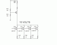
OK John, you've got me confused now. Your earlier designs had what I would call a "sideways H", although the individual source resistors were essentially zero ohms:
http://www.marklev.com/JC2/jc2schematics.jpg (Output Amplifier Module)
http://www.marklev.com/JC3/jc3schematics.jpg
Have your newer designs switched to what I call an "H" input?
http://www.marklev.com/JC2/jc2schematics.jpg (Output Amplifier Module)
http://www.marklev.com/JC3/jc3schematics.jpg
Have your newer designs switched to what I call an "H" input?
Attachments
Charles,
I can't seem to load your PDF. It's coming up blank.
Both,
Yes, the JC-2 and JC-3 use what I am calling a sideways H. I've used that topology, but have not used a vertical/normal H.
I'd be interested in either or both of you commenting on pros and cons of the two Hs.
Grey
I can't seem to load your PDF. It's coming up blank.
Both,
Yes, the JC-2 and JC-3 use what I am calling a sideways H. I've used that topology, but have not used a vertical/normal H.
I'd be interested in either or both of you commenting on pros and cons of the two Hs.
Grey
john curl said:Did I violate a patent?
😀 😀 😀
don´t think so, the H (vertical if you want) configuration is common knowledge. I found it in a book from the 70ties!
Advantage is, that you can taylor the open loop gain independent of Ids, wheras in the Sideways H both items form a linear relationship with all the disadvantages of such a relationship.
Uli


I found it in a book from the 70ties!
Can you pls mention the book title/author?
Hi dimitri,
one book is "Handbuch der Audioschaltungstechnik" by Paul Skritek from the mid 80ies, the other one is from "Franzis Verlag" I have to look up, as this book is at my father´s place.
Uli


one book is "Handbuch der Audioschaltungstechnik" by Paul Skritek from the mid 80ies, the other one is from "Franzis Verlag" I have to look up, as this book is at my father´s place.
Uli


john curl said:Grey, it is again a language problem. 51 ohms gives low Iq and slightly higher noise. 10 ohms gives optimum Iq, BUT not optimum degeneration, so you have to add the 5th resistor of 200 ohms or so.
John, 10 Ohms is the optimum value I guess for a line level input or so (0 / -10db), but will you also use this value for lower levels, mic or an MC preamp? I would use a smaller value (gain, linearity and noise purposes) but not less than 3.3 Ohms, as in the example below:
MC preamp Part2
I think that many of us (me at least) biased by the picture expected a very specific input stage arrangement ! Probably why so many questions about it !!!
I know a famous example similar to yours but with 2x 2SK147/2SJ72 at the input. They feature 6R19 from the junction of the 2 sources to gnd. From One source junction to the other there is a 20R trimmer with wiper to gnd. In total is this about 7,5 - 8R from each source to gnd and this circuit is one of the most famous phono input stages.
Nelson Pass used 22R but for 2SK170GR.
Uli


Nelson Pass used 22R but for 2SK170GR.
Uli


Actually I think that it is somewhat difficult to get an exact value for every source condition. This is because it depends on how hard the input stage has to work in order to give reasonable output to the outside world, and what the source impedance is in front of the fet.
It is possible and practical, in many situations, to slightly forward bias the fet, IF the source resistance is reasonably low. If it is very high, let's say: Above 100kohm, then maybe, forward biasing is a little dangerous. It is very interesting that with very low impedance drive, fets will forward bias and still work very well. Tubes do much the same thing.
It is possible and practical, in many situations, to slightly forward bias the fet, IF the source resistance is reasonably low. If it is very high, let's say: Above 100kohm, then maybe, forward biasing is a little dangerous. It is very interesting that with very low impedance drive, fets will forward bias and still work very well. Tubes do much the same thing.
uli said:
Nelson Pass used 22R but for 2SK170GR.
I believe he said he was using 2SK170BL devices.
Grey
Hi John,john curl said:.................
It is possible and practical, in many situations, to slightly forward bias the fet, IF the source resistance is reasonably low. ............. It is very interesting that with very low impedance drive, fets will forward bias and still work very well. Tubes do much the same thing.
could you explain this forward bias and how it differs from ordinary bias?
How do we set up a circuit to achieve one or the other?
positive Vgs in case of NFET as long as you stay below the voltage to turn on the GS Junction.
Uli


Uli


GRollins said:I believe he said he was using 2SK170BL devices.
I wonder how he manages a draincurrent below 3mA per device with 22R and BL type
😉
Uli


Attachments
I'm not sure where you're getting the 3mA figure. It's been a while since I looked at the Ono schematic, but I seem to recall that they're running at around 5mA each.
Grey
Grey
Grey,
Between the base of the cascode and Vb are about 13Volt. When you look at the resistor between collector and Vb being 1k its not possible to have a collectorcurrent higher than about 12mA.
Uli


Between the base of the cascode and Vb are about 13Volt. When you look at the resistor between collector and Vb being 1k its not possible to have a collectorcurrent higher than about 12mA.
Uli


- Status
- Not open for further replies.
- Home
- Amplifiers
- Solid State
- John Curl's Blowtorch preamplifier

