What I found important in this review, is that a power conditioner was necessary to make the amp work in his environment. I am not really surprised, since I use a toroid power transformer and only regulate the driver stages. I believe in power conditioners. However, it is difficult to make a satisfactory power conditioner for such a big amp.
Not everybody needs a power conditioner. We have known this for years by designing and using power conditioners.
If I were to make a mk2 version of the Parasound JC-1, I would like to add some power supply filtering, just like Ayre does already, and I would lower its static noise, as recommended by Bob Cordell. I would LOVE to use a split-C core, but I doubt that I could get away with it, with Parasound amps. Charles has taken this further than me, and he has succeeded.
I want to give all of you the design of a really cheap power conditioner. Get a 10uF polypropylene metal cased motor start capacitor between 400DCV and 600V and plug it directly across the hot and the neutral at the wall. If this does not help your sound, you don't need a power conditioner. That's what I do.
Also, I would like to thank PMA and others for pointing out the 6 Moons review, especially the residual hum. I doubt that it would be audible, but it is something to work on to improve the design.
Magura said:I was fortunate enough to head straight for the conclusion...and after reading his conclusion, I didn't feel any need to read the rest 😀 Magura 🙂
I'd be very curious as to the quality of the mains getting to the system. If it needed the amount of "conditioning" to get it to sound acceptable I'd guess it was your typical daisy chained/push connection or ancient, hasn't been touched since the house was built, AC supply.
Monitoring the mains at the outlet is an interesting educational experience. I'd suspect most audiophiles would be blown away at having their circuit breaker changed and tightening the screws on the outlets and at the breaker box. Actually A dedicated line will make most power conditioners un-necessary; although there needs to be a disclaimer here as to how trying any of this will kill you if you're inept. Also none of this is as cool as buying power regeneration system.
Hooking up a pair of amps with this type of power demands requires knowing you mains can handle it. From the sound of the review it couldn't.
I wouldn't roll over so quickly John.😉 If your supplies are working as designed, they're ignoring most of the high frequency garbage but can't be expected to perform at their peak with a choke hold on the power.
Regards, Mike.
john curl said:especially the residual hum.
This is another clue as to a mains problem.
Regards again, Mike.
Hi John,
With regulated driver stages (I assume you are including the voltage amplification stages also), you should not have any noise problems at all. Possibly layout, but you nailed the power issues where it was needed.
My setup includes two circuits, one direct for the power amps and one through a filter to all signal stages. It's a new (6 years old now) 200 amp service and box. Both circuits are on the same phase.
If someone makes a living at evaluating audio, I can't understand why they would (for less that $1,000 I bet) not install dedicated AC mains straight to the panel. This must be less expensive than installing all the toys. How much would an extra isolation transformer cost? I guess it isn't shiny, so it doesn't get considered with most of these guys. At any rate, that eval is a mess. You should be questioning the method John.
-Chris
John,
I greatly appreciate your attitude shown in Post #1981.
Thank you and best regards,
Pavel
I greatly appreciate your attitude shown in Post #1981.
Thank you and best regards,
Pavel
I guess it isn't shiny
But it can be 🙂

9 Audiophile quality breakers all 32 amp Seimans German made and polished breakers. High purity copper bus bar, high quality copper cables. etc. etc.
Regards
James
I used to think, perhaps ten or fifteen years ago, that all this AC isolation stuff was impossibly silly; that even if audible, it wouldn't apply to me. And that, mind you, is with me being fairly far out in the tweak direction. I figured that transients would be adequately filtered by the power transformer's inductance and that surely RF and such would be filtered sufficiently by the power supply capacitance...etc.
However, I have a rigid policy of saying 'no comment' if I haven't tried something, rather than condemning things just because I can't see how they might make a difference. Being notoriously frugal, I was reluctant to spend money on something that I didn't think would accomplish anything. On further reflection, I realized that I could cobble a decent one together out of parts I already had on hand.
Rather than drag it out, I'll simply say that I became an instant believer in passive AC mains filtering. It's not all that hard--or expensive--to DIY and makes a disproportionate difference, per dollar spent, in the sound quality.
What made it easier was that I didn't have to back off of some pre-conceived notion that it was a stupid idea. I've never been fond of the taste of crow.
Grey
For the DIYer it should be fairly easy to find something from Corcom http://www.corcom.com/ (now Tyco), Schaffner http://www.schaffner.com/ or others to use as a power line/power entry filter into their amplfiers etc. It should be mandatory to use.
Maybe also use some MOVs to take overvoltages etc.
It is a pooluted world, also EMI/RFI/electricity-wise.
RK
Maybe also use some MOVs to take overvoltages etc.
It is a pooluted world, also EMI/RFI/electricity-wise.
RK
Re: Modified JC 80
Why this bias scheme for the complementary differential input JFET stage, and not something like this, as e.g. used by Borbely?
RK
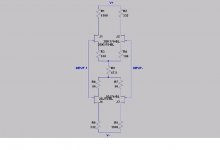
Justcallmedad said:… Just a global attempt to update the JC80 for fun, with today’s components.
Resistors values are changed to fit the Irf devices requirements and to reach a 20kHz bandwith in open loop.
The 2SK389 and 2SJ109 can be replaced by the 2SK170/2SJ74 of course, but also by other ones as suggested by JC, in this case R2/R3/R14/R15 must be adjusted. In my case the SK 389/SJ109 Idss value is 10 mA. Mosfets Idle Id is 50 mA. I changed the original input stage arrangement for this preferred one. It just a starting point, probably the MASTER will see some possible improvements. I didn’t build it, some measurements with real devices could lead to various modifications .
Gain 12dB.
Zout 50R per side.
An externally hosted image should be here but it was not working when we last tested it.
The DC servo could be something like the one I post about the Blowtorch in this post
Why this bias scheme for the complementary differential input JFET stage, and not something like this, as e.g. used by Borbely?
RK
Attachments
GRollins said:I used to think, Rather than drag it out, I'll simply say that I became an instant believer in passive AC mains filtering. It's not all that hard--or expensive--to DIY and makes a disproportionate difference, per dollar spent, in the sound quality.
What made it easier was that I didn't have to back off of some pre-conceived notion that it was a stupid idea. I've never been fond of the taste of crow.
Grey
This why we experiment with things. I don't easily call bull on concepts without experimenting. What we're discussing is effective power supply rejection of all types of mains noise, not to mention inductive and capacitive coupling of noise that gets into the signal path.
I don't doubt that filtering works and is audible, but what does this say about the component in question? I will also agree that it's tough to completely dial some of these influences out.
Actually this is off topic
Regards, Mike.
mike:
i especially agree about the part on tightening screws at the outlets, breaker box, etc. depending on your circumstances, it can make an observable (audio-wise and o'scope-wise) difference.
mlloyd1
i especially agree about the part on tightening screws at the outlets, breaker box, etc. depending on your circumstances, it can make an observable (audio-wise and o'scope-wise) difference.
mlloyd1
MikeBettinger said:... I'd suspect most audiophiles would be blown away at having their circuit breaker changed and tightening the screws on the outlets and at the breaker box
Many here are unfamiliar with the need and application of power line filters. It is not as easy as adding a Corcom filter. If you insist on believing this, I have a bin full of Corcom filters for sale.
Of course, it appears to be an intelligent approach, but I found out about 25 years ago, that stock filters don't always do the sound any favor.
Back in 1982, I designed a power supply for a master recorder for Dave Wilson. In front of the power supply, I placed a super, military grade, sealed power line filter. About 1 year later, Dave Wilson took it out and gave it back to me. Apparently it effected the sound. Instead, Dave bought some high grade isolation transformers to be in series with the power supplies.
For power line isolation, we tend to reject MOV's and commercial filters.
We prefer gas filled tubes, isolation transformers, custom filters, and Bybee devices.
(Bork, bork, borK)

Neither input stage approach is completely optimum. The 3.3 ohm resistors are a little small, I would increase them to 4.7 ohms, just for safety. It keeps the input diode less prone to forward conduct. I usually prefer 10 ohms.
The other approach turns off the fets, and I doubt that you can get 1 ma each from the input devices with this approach.
I design with both configurations, depending on the quality of the design.
The other approach turns off the fets, and I doubt that you can get 1 ma each from the input devices with this approach.
I design with both configurations, depending on the quality of the design.
john curl said:,
We prefer ......................, isolation transformers, .......................
(Bork, bork, borK)
Do you feel an isolation transformer alone is a worthwhile addition?
Thanks...
I was last insulted by Bork, bork, bork' on this website when I last mentioned serious audio design considerations. It comes from the 'Muppet's Swedish puppet sayings'
Re: Re: Modified JC 80
This arrangement allows a higher bias for better linearity, higher bandwidth, and less noise than a standard configuration.
R-K Rønningstad said:
Why this bias scheme for the complementary differential input JFET stage, and not something like this, as e.g. used by Borbely?
RK
This arrangement allows a higher bias for better linearity, higher bandwidth, and less noise than a standard configuration.
Hi, Justcallmedad,
About the schematic in post #1923, I've got some questions :
1. What is the function of R7 (220R to ground)?
2. Why you don't put degeneration (about 22-47R) on sources of J3-J4 (like usually done for self-biasing Jfets)?
Hi, Mr.Curl,
Still about this post #1923 schematic, if the input and output are only single-ended, it seems possible to make a preamp with just 1Pfet and 1Jfet in self-biasing mode, like Justcallmedad's.
What's the difference between this approach and use full complementary Jfets, 2Pfets+2Nfets (like Dennesen JC80)?
john curl said:Many here are unfamiliar with the need and application of power line filters. It is not as easy as adding a Corcom filter. If you insist on believing this, I have a bin full of Corcom filters for sale.
Of course, it appears to be an intelligent approach, but I found out about 25 years ago, that stock filters don't always do the sound any favor.
Back in 1982, I designed a power supply for a master recorder for Dave Wilson. In front of the power supply, I placed a super, military grade, sealed power line filter. About 1 year later, Dave Wilson took it out and gave it back to me. Apparently it effected the sound. Instead, Dave bought some high grade isolation transformers to be in series with the power supplies.
For power line isolation, we tend to reject MOV's and commercial filters.
We prefer gas filled tubes, isolation transformers, custom filters, and Bybee devices.
(Bork, bork, borK)
Thank you for the reply. For the record, I do not mean it is just as easy as picking, say, a filter from a PC PSU, or just any Corcom filter. But it is of interrest to hear about your experiences with this.
If you could care to share some more of your insight I would be grateful. There are many ways to skin a cat so I do not expect you to exactly tell what you do in this and that product. In fact, I expect you NOT to.
🙂
Thanks for informing about the Bybee, I assume it must be these http://www.bybeeconnection.com.
Best regds
RK
lumanauw said:Hi, Justcallmedad,
About the schematic in post #1923, I've got some questions :
1. What is the function of R7 (220R to ground)?
2. Why you don't put degeneration (about 22-47R) on sources of J3-J4 (like usually done for self-biasing Jfets)?
Hi, Lumanauw,
1) R7 set the gain; it is « local » feedback or degeneration.
2) I use high Id on fet’s, higher source resistors lowers Id. (Idss from 12 to 16 mA / V range).
High Id lead to best measures as well as better sound, however John is right, 3,3R is on the low side for a power amplifier input, I normally use these values for mic preamps or phono inputs, more usually on low to medium inputs levels, -80 to -20dB.
- Status
- Not open for further replies.
- Home
- Amplifiers
- Solid State
- John Curl's Blowtorch preamplifier