Many good results can be found on 'Google' What is necessary is to pay attention to this defect in cheaper rectifier diodes.
PMA said:John speaks about recovery time and shape of undershoot when diode turns off.
Wavebourn speaks about reshaping it by ceramic capacitors, and adds a shape of currents that charge tanks. Also, discusses how that currents can contaminate the ground causing voltage drops.
john curl said:Many good results can be found on 'Google' What is necessary is to pay attention to this defect in cheaper rectifier diodes.
As well as confirmation that bees are good (keyword: "bees honey health"), and bees are bad ("bees bite death")
john curl said:I would like to return briefly to 'diode reverse recovery voltage' as I think that it is still not well understood and often ignored effect.
First, most common diode bridges have standard diodes. These diodes have many qualities, but they do not turn off very quickly and leave a 'glitch' at every zero crossing of the voltage across them. This is because this 'glitch' might be thought, at least partially, as an AC signal that gets past the diode array itself. Then, the filter caps become coupling caps, and where do they couple? The ground! Not the 'earth' but an arbitrary point of reference inside the electronic circuit. Can we measure it? It is difficult because the 'ground' has no reference to measure itself. However, when you couple the 'grounds' of 2 pieces of equipment, then maybe some extra flow of energy due to these 'glitches' generated by the diodes, might be possible. Still, difficult to measure, but I consider it important enough to be considered.
Hi John,
You stated earlier that you do not use a center-tap, so in your designs the ground would be quasi-virtual and based on the response of the diodes in the two bridge rectifiers and filter caps. It would not absorb any glitch as effectively as a hard wired ground return to the opposite phase of the secondary winding.
The path for the charging currents and any glitches is (I'm assuming things here, but you do use +/- supplies so a ground reference of some sort is implied) through the filter cap-through the one of the diodes-to the opposite phase of the secondary winding that supplied the cycle that created the charging current and glitch. The glitch is created while the diode is conducting. How well it's returned to the secondary winding is based on the conduction of the reverse diode to the opposite phase of the secondary. A properly placed current probe will verify this.
If a center-tapped transformer was being used the story would be different. The same cycle would occur but the return path for the charging cycle and the glitch would be through the cap back into the secondary. As long as the secondary is properly executed and the transformer leads are not excessively long the system can work quite well.
Also how the two halves of the supply are connected together to create the ground reference will determine how contaminated the ground will be by this mechanism, in either case.
I’ve experimented with both approaches and sonically, when both approaches are implemented the same; I prefer a center-tapped approach. I hear the effect on strings and the purity of voices.
Mike
There are 2 capacitors, Mike, one for +, one for -. They need to be connected together by a wire. In both cases: centertapped or not, the same voltage drop will happen on this wire, between capacitors, during huge current peaks. However, with center tapped transformer the central point between capacitors will be more central since capacitors are not identical.
Wavebourn said:There are 2 capacitors, Mike, one for +, one for -. They need to be connected together by a wire. In both cases: centertapped or not, the same voltage drop will happen on this wire, between capacitors, during huge current peaks. However, with center tapped transformer the central point between capacitors will be more central since capacitors are not identical.
I understand this.
I'm trying to discuss something a bit more subtle than this. Think about the loop that is created with the secondary, the diode, and the filter into the opposite phase of the secondary winding (think of only the positive side of the supply for now).
In reality this loop is where you want to contain the charging currents and any glitches. For lack of a better way to describe it (by me), if this loop is properly implemented none of the effects of either of these two should circulate through the signal path or be impressed upon the circuit ground reference. This is the part I find critical because this ground reference is used by both the input and feedback circuitry.
I'm only talking about when the diodes are conducting, turning on or turning off.
Mike.
As soon as they are glitches they are reflected on the second half of the secondary, and on the primary as well.
Yes, you can assume that the point in the middle between capacitors is the ground and nothing can "contaminate" it, because it is a reference point. Ripples on + and - rails are ripples on rails. They have nothing to do with ground, except they are measured in respect to the ground.
Now, let's go further and see what happens if we decide to add a power filter between an outlet and a primary of a power transformer, consisting of pair of double chokes and 3 pairs of Y-connected capacitors. Take the last one, closer to the primary of the transformer.
We have a "hot" wire and a "cold" wire. Cold one is actually ground, but it is not the same wire as the ground one that goes to the same outlet. This wire has own inductance and resistance.
Currents that flow through capacitors are proportional to frequency, right? The higher is the frequency, the higher are current peaks. Acting as a voltage divider that capacitors supply the ground wire that goes to the outlet by up to half of the voltage of spikes between "hot" and "cold" wires.
Did a filter help us?
No. It translated spikes of currents created by rectifiers into spikes of voltage drops on the chassis.
What happens now if we connect 2 devices, a preamp and a power amp, by a unbalanced cable with sockets designed by RCA a millennium ago? Right, due to different potentials of spikes on different ends of cable shields that spikes will enter power amplifier's output.
Even if we use electronically balanced outputs and inputs it won't help much: CMRR of such "balanced" inputs on high frequencies make my slippers laugh.
So, how did we create the problem?
Easy: we bought and installed a very good, UL-certified super-duper mains filter, in order to make our gear better. Congratulations! 😀
Wavebourn said:As soon as they are glitches they are reflected on the second half of the secondary, and on the primary as well.
Yes, you can assume that the point in the middle between capacitors is the ground and nothing can "contaminate" it, because it is a reference point. Ripples on + and - rails are ripples on rails. They have nothing to do with ground, except they are measured in respect to the ground.
Now, let's go further and see what happens if we decide to add a power filter between an outlet and a primary of a power transformer, Did a filter help us?
No. It translated spikes of currents created by rectifiers into spikes of voltage drops on the chassis.
What happens now if we connect 2 devices, a preamp and a power amp, by a unbalanced cable with sockets designed by RCA a millennium ago? Right, due to different potentials of spikes on different ends of cable shields that spikes will enter power amplifier's output.
😀
I would agree with your assessment of the effect of placing a filter between the mains input and the primary, but I disagree with the secondary side description.
The ripple or glitches on the rails can be effectively filtered and kept off of the rails if the loop I outlined is working properly. Fundamentally, if this scenario did not work, placing a 10000uf cap from the rail to ground would not filter the mains ripple. Why should the same loop not be effective at filtering other artifacts of the rectification process, or better yet, noise on the secondaries from the primary side? Why would we return RFI filtering to this same “ground reference” if we didn’t expect it to magically eliminate the offending noise somehow?
My point is, the execution of this very critical loop determines its effectiveness in dealing with secondary noise artifacts, contamination of the ground and the effectiveness of the ground net at sinking RFI.
Containing ripple, rectifier glitch artifacts, and mains noise at the transformer secondary can be accomplished by controlling this loop, and that the center-tap plays a bigger role than has been alluded to over the past couple of years here.
Mike.
Mike;
Please explain once more, a bit slower this time: what happens with currents and voltages? I could not understand what do you mean.
Please explain once more, a bit slower this time: what happens with currents and voltages? I could not understand what do you mean.
The speculation is leading in circles. I suggest assembling a pair of supplies and looking at the interactions with a current probe.
However, I contend that there is more noise leakage through the primary-secondary capacitance than the sub microsecond reverse conduction of the diodes. The diode conduction is a low level wideband noise source. The capacitive coupling is always there and can have considerable current. Its pathway back to the ground reference of the circuit has a lot to do with its influence on the sound. The late Bob Crump was obsessed with this, which is why he insisted that I got the primary wiring on the Number Cruncher supply reversed on one supply.
I try to reduce it by using a single floating supply with a current source output driving stacked shunt regulators. Very non-green but it does create a high impedance between the raw supply and the circuit.
MikeBettinger said:
I’ve experimented with both approaches and sonically, when both approaches are implemented the same; I prefer a center-tapped approach. I hear the effect on strings and the purity of voices.
I have done the same experiment, more than once, with the opposite observations 🙂
john curl said:[snip]This is because this 'glitch' might be thought, at least partially, as an AC signal that gets past the diode array itself. Then, the filter caps become coupling caps, and where do they couple? The ground! Not the 'earth' but an arbitrary point of reference inside the electronic circuit. Can we measure it? It is difficult because the 'ground' has no reference to measure itself. [snip]
John, you are right in this of course. But isn't that the whole point behind correct (star) grounding? You try to set up the ground system such that the diode glich current (or any other disturbance for that matter) does NOT lead to an unwanted signal on any ground that is shared by a signal reference. In other words, make sure that your mentioned 'arbitrary point of reference' is identical to the supply return and signal reference. When you do that, the ground can be measured against itself, so to speak, because the ground is it's own reference. Consequently, the disturbances disappear.
Jan Didden
Wavebourn said:Mike;
Please explain once more, a bit slower this time: what happens with currents and voltages? I could not understand what do you mean.
Take a look at these two images.
Attachments
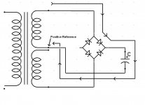
And. Hopefully this clarifies the point I was making between the John's approach without center-tap and with center-tap and that the effectiveness of any filtering (mains or higher frequency on the secondary) will be affected by the implementation of the path to the reference, which is what I believe Jan is saying.
Mike.
Mike.
Attachments

analog_sa said:I have done the same experiment, more than once, with the opposite observations 🙂
Just goes to show that, as in all things, YMMV 😉
There are too many variables to attempt a guess why this would be as it is.
Mike.
1audio said:Its pathway back to the ground reference of the circuit has a lot to do with its influence on the sound. The late Bob Crump was obsessed with this
What I'm saying relates to this.
Mike.
Confusion I guess
I guess I'm not being understood.
I'm commenting on John's post about diode switching noise and his suggesting that it could be contaminating the ground.
My comments were basically saying that, I agree that it can happen but, if the ground reference is working it should filter out this switching noise from the diodes through the filters (and their bypass caps). With a little care the noise (as well as any mains residual (60/120hz) does not have to contaminate the ground reference or circulate on any of the circuit grounds; or between components in a system.
It's my experience that the center-tapped design does a better job at this and the two images show the loop paths of both the center-tapped rectifier loop and the bridge derived ground reference loop. The second image illustrates the diode in series with the latter. From current probe measurments on this leg of the loop it is a less than perfect ground return for these currents relative to a center-tap arrangement.
I did not show the negative side because as far as what's happening at the bridge output it is irrelevent; as all of it's noise and charging currents are contained within the other secondary loop.
Hopefully this clears it up. If not we can let it go and move on.
Mike.
Mike and Jan, it is not that star grounding removes the potential for an internal ground loop, what about other grounds that this 'ground is connected to? Then, your ground is not so solid anymore, BECAUSE it is not its own reference, then. Measuring with your own ground as reference is the problem. Then, star grounding removes any signals going to ground from dropping being picked up by the unit itself, but all 'grounds' are artificially derived, so that when you connect them together, who knows what garbage flows between components, then?
As far as center tapping is concerned: I first removed the center tap as an experiment in making an 'improved' version of a power supply for a Threshold preamp. It was so successful, that I changed all my Vendetta power supplies to this and called it the A version of the Vendetta. One thing that I could actually measure was a potential ground loop that the ground lift removed. It is not always possible to remove the center tap, because it requires VERY symmetrical current loading. Sometimes it is more useful to put a 5mH air core choke in series with the center tap. I do that in several designs. This allows DC asymmetry, yet tends to block AC from the center tap getting into the ground.
As far as center tapping is concerned: I first removed the center tap as an experiment in making an 'improved' version of a power supply for a Threshold preamp. It was so successful, that I changed all my Vendetta power supplies to this and called it the A version of the Vendetta. One thing that I could actually measure was a potential ground loop that the ground lift removed. It is not always possible to remove the center tap, because it requires VERY symmetrical current loading. Sometimes it is more useful to put a 5mH air core choke in series with the center tap. I do that in several designs. This allows DC asymmetry, yet tends to block AC from the center tap getting into the ground.
- Status
- Not open for further replies.
- Home
- Amplifiers
- Solid State
- John Curl's Blowtorch preamplifier