1audio said:
Actually I really meant that the original music as played in its original space was not all that wonderful. Often our memory of the experience doesn't really match the actual experience and many well revered recordings were not such a great experience in the "making". A good recording engineer can pull a recording with a more satisfactory sound than that heard at the session.
Exactly! Many live recordings are remembered because of the event and venue, without realising that the musical performance as such wasn't that hot. And a recording of that same piece can be much more rewarding, musically.
I have said again and again that the recording and reproduction processes are arts in and of themselves. Continuously comparing a recording to a live event is not only comparing apples to cartwheels, but also does not do justice to the many excellent recordings out there.
And yes, you can't reproduce the sound level of an organ in your home. But then stop trying for pete's sake and stop lamenting that it doesn't sound like the real thing. Of course it doesn't. So what?
Jan Didden
john curl said:I once heard church organ done very well.
Reminds me of that 2nd hand organ LP I once had. The title was: 'Bach's organ works'. Someone had scribbled on it: 'mine too!'. 😀
Jan Didden
Originally posted by janneman
I have said again and again that the recording and reproduction processes are arts in and of themselves.
There's no argument about it.
Originally posted by janneman
And yes, you can't reproduce the sound level of an organ in your home. But then stop trying for pete's sake and stop lamenting that it doesn't sound like the real thing. Of course it doesn't. So what?
Jan Didden
My aim with my sound system is to come as close as possible, with my limited means. However, knowing that the sound cannot possibly reproduced accurately relieves some frustrations.
Joshua_G said:My aim with my sound system is to come as close as possible, with my limited means. However, knowing that the sound cannot possibly reproduced accurately relieves some frustrations.
What part of the money you spend on audio do you spend on improving room acoustics? And how did/do you improve your room acoustics?
Jan Didden
janneman said:
What part of the money you spend on audio do you spend on improving room acoustics? And how did/do you improve your room acoustics?
Jan Didden
Extremely valuable point. For all the discussion on esoterica, the greatest improvement in my sound system comes from shutting the listening room door. Next to that simple stuff such as heavy curtains (is that drapes to Americans?) over the windows and other simple stuff. This may be obvious to some, but not necessarily so judging by the pictures some posters have made elsewhere.
Re: Re: Re: Re: Re: Re: VAS fighting
Hi Glen,
You are quite right in pointing out the “LTP fighting” issue. This is another shortcoming of the complementary input pair architecture. One who uses this architecture and expects to get good performance must use reasonably matched differential pairs in its implementation.
This is true for any design using this architecture, not just the one I showed. The degree to which a mismatch will cause a problem in regard to VAS bias current accuracy is proportional to the voltage gain of the input stage. In a design with a less crippled VAS, this gain can be quite high. In run-of-the-mill implementations that merely employ a single-ended resistor load on each LTP, this gain is fairly low.
In the design example I showed, the input stage gain is quite high, on the order of 40 (20k divided by the emitter-to-emitter resistance of 500 ohms). The VAS bias current perturbance caused by a mismatch in a single pair will be approximately the mismatch voltage times the input stage gain times the VAS transconductance, all divided by two.
Even apart from the VAS bias current issue, having mismatched LTPs essentially connected in parallel and fighting each other is a bad thing, since it forces the pairs to be out of balance. As we know, LTPs provide the lowest distortion when they are in balance. This is one of the reasons that loading the LTP with a current mirror in any architecture is usually a good thing.
I always employ matched LTPs in a single package in my amplifier designs (whether the LTPs are BJTs or JFETs). For BJTs the mismatch will generally be less than 1 mV, while for JFETs it will generally be less than 5 mV. In the example I showed, a 1 mV mismatch in the BJT LTP will result in a VAS bias current change from design nominal of about 7%. I usually believe that the VAS bias should be kept within 10% of the target value, so that design is perfectly fine as long as I adhere to my LTP matching criteria. If you use ADI MAT04 and ADI SSM2220 matched transistors for the NPN and PNP LTPs, respectively, you will easily meet these matching criteria. I think these parts are about $3 each.
Indeed, anyone foolish enough to use LTPs mismatched by 15 mV in the design example I showed will suffer the consequences.
For those who wish not to use matched devices, then they must cripple the VAS more than I have shown. This is easy to do with my circuit. The 20k resistors across the collectors of each LTP can simply be reduced in value.
For those who want to use discrete parts for the LTPs (and incur possible minor temperature differences), parts like the 2N5551 from the same batch are easily hand-matched to within less than 2 mV because so many are close to begin with.
The complementary input architecture will work fine for those who pay adequate attention to LTP offset matching, LTP gm matching, and matching of twin Miller capacitances (including effects of different VAS collector-base capacitances where that applies). The unipolar architecture is not nearly so vulnerable to these concerns, and in most cases does not require one to cripple the VAS to achieve good VAS bias current stability. The unipolar architecture I use and that others like Holman have used provides fully complementary push-pull VAS.
Bear in mind, this discussion came up when it was asserted that the complementary architecture was superior to the unipolar architecture. While comparisons usually are best made on a case-by-case basis, the shortcomings we have discussed here show that, at minimum, such a generalization is plainly wrong.
Cheers,
Bob
G.Kleinschmidt said:
Bob, I understand exactly how the circuit works and the different values of emitter degeneration resistors are to account for the differences in Vbe between the NPN and PNP transistors.
This is one way to avoid the Slone problem, however you are missing the point. The large gain of the LTP's makes the circuit excessively sensitive to an input offset imbalance between the LTP's.
Do the experiment I showed here in post 16874 to see for your self just how small an imbalance is required to throw the VAS bias out:
http://www.diyaudio.com/forums/showthread.php?postid=1793473#post1793473
BTW, you are not the only one:
http://www.diyaudio.com/forums/showthread.php?postid=1654719#post1654719
Cheers,
Glen
Hi Glen,
You are quite right in pointing out the “LTP fighting” issue. This is another shortcoming of the complementary input pair architecture. One who uses this architecture and expects to get good performance must use reasonably matched differential pairs in its implementation.
This is true for any design using this architecture, not just the one I showed. The degree to which a mismatch will cause a problem in regard to VAS bias current accuracy is proportional to the voltage gain of the input stage. In a design with a less crippled VAS, this gain can be quite high. In run-of-the-mill implementations that merely employ a single-ended resistor load on each LTP, this gain is fairly low.
In the design example I showed, the input stage gain is quite high, on the order of 40 (20k divided by the emitter-to-emitter resistance of 500 ohms). The VAS bias current perturbance caused by a mismatch in a single pair will be approximately the mismatch voltage times the input stage gain times the VAS transconductance, all divided by two.
Even apart from the VAS bias current issue, having mismatched LTPs essentially connected in parallel and fighting each other is a bad thing, since it forces the pairs to be out of balance. As we know, LTPs provide the lowest distortion when they are in balance. This is one of the reasons that loading the LTP with a current mirror in any architecture is usually a good thing.
I always employ matched LTPs in a single package in my amplifier designs (whether the LTPs are BJTs or JFETs). For BJTs the mismatch will generally be less than 1 mV, while for JFETs it will generally be less than 5 mV. In the example I showed, a 1 mV mismatch in the BJT LTP will result in a VAS bias current change from design nominal of about 7%. I usually believe that the VAS bias should be kept within 10% of the target value, so that design is perfectly fine as long as I adhere to my LTP matching criteria. If you use ADI MAT04 and ADI SSM2220 matched transistors for the NPN and PNP LTPs, respectively, you will easily meet these matching criteria. I think these parts are about $3 each.
Indeed, anyone foolish enough to use LTPs mismatched by 15 mV in the design example I showed will suffer the consequences.
For those who wish not to use matched devices, then they must cripple the VAS more than I have shown. This is easy to do with my circuit. The 20k resistors across the collectors of each LTP can simply be reduced in value.
For those who want to use discrete parts for the LTPs (and incur possible minor temperature differences), parts like the 2N5551 from the same batch are easily hand-matched to within less than 2 mV because so many are close to begin with.
The complementary input architecture will work fine for those who pay adequate attention to LTP offset matching, LTP gm matching, and matching of twin Miller capacitances (including effects of different VAS collector-base capacitances where that applies). The unipolar architecture is not nearly so vulnerable to these concerns, and in most cases does not require one to cripple the VAS to achieve good VAS bias current stability. The unipolar architecture I use and that others like Holman have used provides fully complementary push-pull VAS.
Bear in mind, this discussion came up when it was asserted that the complementary architecture was superior to the unipolar architecture. While comparisons usually are best made on a case-by-case basis, the shortcomings we have discussed here show that, at minimum, such a generalization is plainly wrong.
Cheers,
Bob
janneman said:
What part of the money you spend on audio do you spend on improving room acoustics? And how did/do you improve your room acoustics?
Jan Didden
Its not so much money, however, my listening room acoustics is treated.
Joshua_G said:
Its not so much money, however, my listening room acoustics is treated.
INHO, better to spend your money on that then on $400 mains cords 😉
Jan Didden
Re: Re: Re: Re: Re: Re: Re: VAS fighting
Okay, that's what I get with 20dB NFB. Matched BC547/BC557. Negligible distortion rise at 10kHz.
Bob Cordell said:While comparisons usually are best made on a case-by-case basis, the shortcomings we have discussed here show that, at minimum, such a generalization is plainly wrong.
Cheers,
Bob
Okay, that's what I get with 20dB NFB. Matched BC547/BC557. Negligible distortion rise at 10kHz.
Attachments
Re: Re: Re: Re: Re: Re: Re: VAS fighting
Bob,
What would you match the JFETs for? Vgs at constant Id? If so, matching for 5mV means matching a typical 2SK170/2SJ74 pair for about +/-0.2mA in Idss. For all practical purposes that's very tight and therefore, unless you are plannign to ask JC to handmatch some devices for you, I would drop JFETs out of this discussion.
Bob Cordell said:
I always employ matched LTPs in a single package in my amplifier designs (whether the LTPs are BJTs or JFETs). For BJTs the mismatch will generally be less than 1 mV, while for JFETs it will generally be less than 5 mV.
Bob,
What would you match the JFETs for? Vgs at constant Id? If so, matching for 5mV means matching a typical 2SK170/2SJ74 pair for about +/-0.2mA in Idss. For all practical purposes that's very tight and therefore, unless you are plannign to ask JC to handmatch some devices for you, I would drop JFETs out of this discussion.
SYN08, you appear to lack experience that both Bob Cordell and I both have. You would be so cheap as to revert to the original AMPZILLA in input stage implementation. Then we could avoid fets, matching, AND we could ADD some electrolytic caps. Maybe a few ceramic caps (cheap ones) as well? That is the summation of suggestions of several here on this thread.
I sure had a lot of fun driving my '54 Chevy, back 50 years ago. Maybe General Motors should just revert to making them, instead of electric cars and such. A few modern engineering enhancements should be OK, but why bother with matching pistons, overhead cams, and such?
Just more effort on the assembly line.
john curl said:SYN08, you appear to lack experience that both Bob Cordell and I both have.
John,
Do you understand what we are talking here about?
I am not into your quibbles of THD differences. I have lots of successful audio product out there that measures OK, if not darn good. A little 2'nd harmonic is the least of my worries.
Actually, unfortunately, even a single FET matched pair has an inherent limitation in that its S curve can bend pretty hard as you approach 2 x Id, as you run out of current available.
The complementary differential bipolar has this problem also, but to a lessor degree.
The H bridge style complementary differential fet removes this problem as the input stage can still continue to operate beyond 2 x Id under transient conditions.
Now a SERIOUS circuit simulator would find the ideal ratio of Id to Rs in an H bridge for smoothest transistion, just like Barney Oliver did for Re vs Gm for complementary output stages.
If anyone want's to try and repeat some of the old Jung/Curl capacitor/resistor quality tests, I tried a little experiment last night.
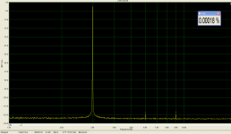
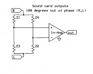
Taking the Left and Right channels on a good sound card and generating a 1K sine wave with one channel inverted made a great differential bridge drive (see picture). There was a good bit of cancellation (at least with my card) and there were no evens above the noise floor. As one can see this configuration can almost eliminate (with trimming) common mode signal on the in-amp. With care it's scary how much resolution you can get, I guarantee it will tax your ability to ground and shield properly.
My sound card showed -106dB of third at 20V p-p differential out, the bridge easily extends that another 40dB (which is only a 1% match).
Attachments
john curl said:
Now a SERIOUS circuit simulator would find the ideal ratio of Id to Rs in an H bridge for smoothest transistion, just like Barney Oliver did for Re vs Gm for complementary output stages.
Actually a serious modling effort would enable (almost) any simulator to do that.
Re: Re: Re: Re: Re: Re: Re: Re: VAS fighting
Hi Syn08,
Yes, I would match JFETs for +/- 5mV at the Id I was using them at in the LTP (or be confident from the datasheet that they will do that). When I have used JFETs, I have usually used the NPD5564. Adequately well-matched N-channel JFETs are readily available from Linear Systems.
However, having said that, I am not as qualified addressing the issue of obtaining adequately matched P-channel JFETs for use in a complementary input stage. To be honest, I have never built a JFET-based complementary input stage. John is the expert there.
How tight the JFETs have to be matched is a design decision that is dependent on the details of the particular circuit and the tradeoffs the designer wants to make.
Cheers,
Bob
syn08 said:
Bob,
What would you match the JFETs for? Vgs at constant Id? If so, matching for 5mV means matching a typical 2SK170/2SJ74 pair for about +/-0.2mA in Idss. For all practical purposes that's very tight and therefore, unless you are plannign to ask JC to handmatch some devices for you, I would drop JFETs out of this discussion.
Hi Syn08,
Yes, I would match JFETs for +/- 5mV at the Id I was using them at in the LTP (or be confident from the datasheet that they will do that). When I have used JFETs, I have usually used the NPD5564. Adequately well-matched N-channel JFETs are readily available from Linear Systems.
However, having said that, I am not as qualified addressing the issue of obtaining adequately matched P-channel JFETs for use in a complementary input stage. To be honest, I have never built a JFET-based complementary input stage. John is the expert there.
How tight the JFETs have to be matched is a design decision that is dependent on the details of the particular circuit and the tradeoffs the designer wants to make.
Cheers,
Bob
Hi Bob,
I agree with your points on matching the transistors in a complementary input pair. Now, from a service perspective on actual production amplifiers using this architecture. We'll exclude John's designs from this as I know he will take exception to what I'm saying in his case. These amplifiers tend to have a "harsh", or "grainy" sound associated with them. When you get one on the bench and remove the input transistors, you will find that most are not matched for beta very well. Stop arguing that beta isn't important if you are about to and hear me out. So, higher DC offsets are measured before you go tearing into these amps as well. After a long session of matching new transistors for the same beta, we install those that match all four (a real pain in the butt!). Each pair is physically connected thermally with thermal compound and heat shrink tubing. This does a good job of reducing temperature differentials. Spark the amplifier back up and your DC offsets magically reduce to 5 mV or less typically. This even though no attempt was made to even measure VBE differences. Once you connect speakers and listen to it, the sound quality is greatly improved, the impression is a much smoother presentation. The measured performance is also improved, agreeing with the subjective evaluation.
This procedure has been repeated many, many times over the course of 25 years or so now. The results are always the same. I do understand why production amplifiers do not have well matched input pairs, but the question would be "why would a manufacturer produce models that require such close matching when they do not intend to do this?".
In contrast, the single long tailed pair seems to suffer less from the same mis-matching. The saving grace here are the production matched dual transistors that are available, and have been for some time. A clear indication that this is important is that the dual parts exist in the first place. Keep in mind that industrial and testing applications are the bigger customers for electronic parts. If they need them, the audio industry can use them. So I would say that there is clear science behind this concept that goes beyond audio applications.
I guess a question for John then. Does Parasound use dual or quad transistor pairs that are available from some manufacturer, or are they matched by hand? I have not seen one of these on the bench yet, although I just recommended one for someone.
-Chris
Re: Re: Re: Re: Re: Re: Re: Re: Re: VAS fighting
Bob,
I was intrigued enough by the "death of JFET matching" thread to run some experiments. In simulation I could trim out even 2:1 Idss variation on an LTP with virtually no THD penalty. I actually built a version of the Schoeps transformerless phantom power mic output circuit with PFET's instead of PNP's. Using 2SJ74's matched 1% vs 30% there was no measured difference in THD after balancing.
Awesome circuit BTW .02% (third only) at 4V p-p out, the .5% point moved out to 12V p-p!
Bob Cordell said:
How tight the JFETs have to be matched is a design decision that is dependent on the details of the particular circuit and the tradeoffs the designer wants to make.
Cheers,
Bob
Bob,
I was intrigued enough by the "death of JFET matching" thread to run some experiments. In simulation I could trim out even 2:1 Idss variation on an LTP with virtually no THD penalty. I actually built a version of the Schoeps transformerless phantom power mic output circuit with PFET's instead of PNP's. Using 2SJ74's matched 1% vs 30% there was no measured difference in THD after balancing.
Awesome circuit BTW .02% (third only) at 4V p-p out, the .5% point moved out to 12V p-p!
- Status
- Not open for further replies.
- Home
- Amplifiers
- Solid State
- John Curl's Blowtorch preamplifier