john curl said:Pointless, but too long.
You should try to understand the concept of ergodism.
Cheers
JPV
john curl said:We, little people, usually have to test by hand. I know that there can be automatic testing, but noise is usually really hard to do quickly. Settling time, etc.
when i visited FM Acoustics Switzerland, they measured all trannies by hand for several data to match them, and for phono stage application they had two specially trained woman which had to listen the kind of noise of every transistor, because their noise measuring may gave equal values, but they could hear a difference ( some noise sounds more dark , other more bright)and matched them this way to get best results.
FM Chief Manuel Huber also measures all capacitors for tolerances and some specs, only the resistors are taken out of the box. Crazy guy, but successfull.
😀
john curl said:Gerhard, I don't think that you understand the whole equation. First, it isn't just the wafer that needs to be tested, but each individual device.
That's what wafer testers are for. Not to check diameter and weight of wafers but to check each individual device and decide if it deserves the drop of epoxy to become a TO-92. But then, testing for noise with the yields you expect will probably not be worth the machine time.
So, if you have bought some ammo packs of epoxy drops (or, even worse: plastic bags) and you want to ennoble them, you're on your own or your Vietnamese kids.
And, selecting parts that are extremals of the whole population might provide you with a selection that has unexpected misfeatures, like an idiot savant.
Hi HKC and Phil,
could you please point me to the application note you're refering to? All I found is a National Semi App-note from '75 describing how to use a LM329 to build a true 0-whatever LM3x7 regulator (instead of 1.3-whatever due to internal reference). I can't imagine you would be interested in that.
Have fun, Hannes
Before things get completely out-of-hand, let me formally state that I have the greatest respect for Scott Wurcer's AD797. In fact, I am now building a new phono stage for Parasound that will use the AD797 as the INPUT op amp directly, without ANY Jfets in front. It is THAT quiet that I can use it for the majority of MC users. Also, instead of using 1 ohm, I am using a 50 ohm resistor in the feedback loop (yes, negative feedback, and lots of it, along with his supercharging cap breakthrough), because I respect that his output stage will work better with less stress, and to me, that implies better sound.
Is my design going to be a perfect example of phono stage design? I don't write the ad copy, but let me say before it comes out, that it is my best approach with IC's that I know how to do, and this design, from the start, is a compromise forced by the fact that the JC-2 preamp initially was designed without a phono stage, and we have very little room to retrofit it in the finished box. This design is a Honda, when I usually am known for designing a Porsche. However, it will be buildable and affordable to the majority of serious phono users, rather than just a few very wealthy or excessively dedicated audiophiles. That is yet another design, and that is what I am actually competing with Syn08, when it comes to noise.
Is my design going to be a perfect example of phono stage design? I don't write the ad copy, but let me say before it comes out, that it is my best approach with IC's that I know how to do, and this design, from the start, is a compromise forced by the fact that the JC-2 preamp initially was designed without a phono stage, and we have very little room to retrofit it in the finished box. This design is a Honda, when I usually am known for designing a Porsche. However, it will be buildable and affordable to the majority of serious phono users, rather than just a few very wealthy or excessively dedicated audiophiles. That is yet another design, and that is what I am actually competing with Syn08, when it comes to noise.
John -- I might think of the Parasound products more like a Boxter -- line-built in a foreign country -- while the CTC products remain the 911 Turbos or GTs. Fortunately both of our Porsche's are old enough to have been built individually in Zuffenhaussen 🙂

h_a
I'll keep looking but the enhanced 317/337 regulator is described in Liner Technology's data sheet for the LT137A. It's called a "High Stability Regulator". You can use the same technique for 317/3372 and the LT 1033/1085 regs. Somewhere there's an application note with more detail....I'll see if I can find it.
I'll keep looking but the enhanced 317/337 regulator is described in Liner Technology's data sheet for the LT137A. It's called a "High Stability Regulator". You can use the same technique for 317/3372 and the LT 1033/1085 regs. Somewhere there's an application note with more detail....I'll see if I can find it.
Hi,
thanks a lot! I just had a look - very interesting! If you could find a more in-detail app-note that would be great as well. I would be interested in the improvement compared to bypassing only the adjustment pin.
Have fun, Hannes
thanks a lot! I just had a look - very interesting! If you could find a more in-detail app-note that would be great as well. I would be interested in the improvement compared to bypassing only the adjustment pin.
Have fun, Hannes
Hannes - the best I can find is the Linear Tech data sheet for the LT137 that I mentioned above (http://www.linear.com/pc/downloadDocument.do?navId=H0,C3,P2050,D1457)
from the LT137 app sheet claims a 6.6x improvement over the standard configuration:
"A high stability regulator is illustrated in the application
circuit shown to the right. The output stability, load regulation,
line regulation, thermal regulation, temperature drift,
long term drift, and noise can be improved by a factor of
6.6 over the standard regulator configuration. This assumes
a zener whose drift and noise is considerably better than
the regulator itself. The LM329B has 20ppm/°C maximum
drift and about 10 times lower noise than the regulator."
Good luck --
Phil
Agree 100% -- I only use them as pre-regs for most audio applications, such as before a shunt reg or a op-amp based regulator like the Sulzer/Jung/Didden..........
it's the LT 1033 data sheets which has the LM 329 as an external reference - Have used for a decade now to good result
John -- I posted the info from LT about 4 or 5 posts above. I've never looked at transient overshoot. Good question since the loop gain is being changed. But I do add C to the adjustment pin to minimize that even though the high-stability schematic does not show a capacitor there.
The problems with IC regulators can be numerous, but for audio I find a few important factors:
One is noise, as the voltage reference usually built into the regulator is not very quiet.
Second is transient overshoot with changes in current loading.
Third, is the limited gain-bandwidth that usually allows very high frequency garbage to flow both ways.
Other factors are actually less important for AUDIO. Such as nominal output impedance and correct DC voltage without adjustment.
Excessive reliance on this sort of regulator directly coupled to audio circuitry, both analog or digital, can be problematic.
Everything's fine.
How about additional active filter (so called 'capacitance multiplier') behind the monolithic regulator? BJT, or MOSFET? Why MOSFET, why not BJT?
Reduces noise and improves HF suppression considerably.
How about additional active filter (so called 'capacitance multiplier') behind the monolithic regulator? BJT, or MOSFET? Why MOSFET, why not BJT?
Reduces noise and improves HF suppression considerably.
For Scott Wurcer
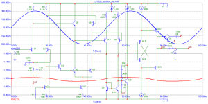
I tried something similar, there is an improvement compared to
http://www.diyaudio.com/forums/showthread.php?postid=1722023#post1722023
I tried something similar, there is an improvement compared to
http://www.diyaudio.com/forums/showthread.php?postid=1722023#post1722023
Attachments
- Status
- Not open for further replies.
- Home
- Amplifiers
- Solid State
- John Curl's Blowtorch preamplifier