john curl said:Well, KBK, my input good enough for you?
I'm reading.....
However, getting the audiophiles (ie, BUYERS) off the 'noise bus' When it comes to understanding what they are hearing..and their near universal aspect of mistaking that for 'reproduction'..well..that is a bit of an ornery and thorny task, at best.
PMA, good to see you here. I was wondering if you could do me yet another favor? IF you could take my patented circuit, simplify it to just 2 complementary idealized devices with no emitter resistors (at first), I would like to know how linear that circuit is below 100mV output. I suspect that you might be surprised (again). If you can't, I will understand.
A friend told me the most sensible thing I can do, as a monkey based creature of habit that likes physical things to work with: Print it. So I did. Much more comfortable to deal with and far more rewarding. Good old paper. Still works when the power goes out.
john curl said:IF you could take my patented circuit, simplify it to just 2 complementary idealized devices with no emitter resistors (at first), I would like to know how linear that circuit is below 100mV output.
John, would you kindly post a link, or send me an image/info by e-mail, just to save my time.
Thanks.
Thanks for the input, John. I appreciate it.
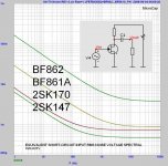
I have a bunch of both the BF861 and BF862 as I thought that I had a found jewels in these. ..
I asked Philips / Sweden about the low freq noise characteristics for them, but got no reply.
80nV / sqrt(Hz) at 1Hz sounds resonable, and my smulations show about 150nV/Sqrt/Hz). Attached.
Sigurd
I have a bunch of both the BF861 and BF862 as I thought that I had a found jewels in these. ..
I asked Philips / Sweden about the low freq noise characteristics for them, but got no reply.
80nV / sqrt(Hz) at 1Hz sounds resonable, and my smulations show about 150nV/Sqrt/Hz). Attached.
Sigurd
john curl said:Sigurd, I think your latest characterization of the BF861 is fairly accurate. I asked again about the number of 80nV/rt. Hz regarding the BF862, and my source backed down a little and told he thought that it was what it measured at 1Hz instead of 10Hz. He was just quoting from memory, but he DID find that they were way out of line for low frequency use, in general. They are really RF devices.
Attachments
PMA, just look at post #5995. Just take one pair of devices, the others are redundant, you can keep the individual emitter resistors if you want, but the battery to cap resistors are usually necessary.
Pretty good for 35 years ago, isn't it? How about the 5 ohm resistors reduced to 1 ohm resistors? Better, worse?
Excellent circuit idea, again.
5 ohm to 1 ohm results in less noise (like 0.24nV/rtHz) and more distortion, about 0.001%.
5 ohm to 1 ohm results in less noise (like 0.24nV/rtHz) and more distortion, about 0.001%.
Please try 10 ohms then, or 1/2 r(e) depending on the Iq of the devices. for example for 1ma Iq, 1/2r(e) would be 13 ohms. for 2ma Iq, 1/2r(e) would be 6.5 ohms, etc.
I was simulating at high Iq of 130mA. Getting down to 15mA increases distortion, but still usable. Low bias as 1.5mA brings high distortion, 0.1%, and also higher noise (I will optimize at 1.5mA).
john curl said:Pretty good for 35 years ago, isn't it?
.............
Most people are more inventive when they are young. 🙂
Cheers,
Edmond.
Is the low noise the result of operating the devices at essentially Vcb=0?
What does this circuit do, actually?
Jan Didden
What does this circuit do, actually?
Jan Didden
- Status
- Not open for further replies.
- Home
- Amplifiers
- Solid State
- John Curl's Blowtorch preamplifier