I think that the best approaches that are published are the one made with the LT1115 by Walt Jung, years ago. The other might be the new phono stage by National Semi. I think that Walt's biasing of the output stage of the LT1115 is a very good idea and I am going to try it. If it works, I might even upgrade the input stage of my ST thd analyzer and even the oscillator (all using Scott's excellent IC's) because I have a tiny 7th harmonic residual that I just can't seem to get rid of.
john curl said:While Scott is trying to reduce IC operating current (and proud of it) and still remain within very good operating specs
According to some customers I hold the record 400mA peak current at only 600uA bias and distortion still holds up at 2.2 MHz.
Many of the people here (using DSL) are surfing through them.
Jim Williams once gave an ISSCC talk on damping dual SU carburators. I left a plug out once and drove around with gas pouring all over the engine.
john curl said:I think that Walt's biasing of the output stage of the LT1115 is a very good idea and I am going to try it.
For the record, it was already old when I was doing it in '84.
hi John,
in the specific instance of using the AD797 in a mc phono preamp input you are complaining that you "have" to give up 12 dB S/N due to the inadequate output drive of the 797 - when 50 cents more in discrete output stage could solve the "problem"
today parts cost, count and board area are the main determinants of manufacturing cost - number of pins on the parts doesn't matter at op amp vs discrete levels
if one op amp has good input specs for the job and another meets the output requirements how is a composite/multiloop op amp circuit different from choosing differing transistors for those functions in a discrete implementation? - and using op amps parts count and board area can go down relative to a all discrete solution
a question is when is class A operation required? - it certainly appears the A/DSL driver op amps can't have measurable audio frequency crossover distortions if they do so well at MHz - is it then just a matter of power supply routing/partitioning to prevent the class B currents from coupling to the other circuitry?
PMA said:For audio line stages, do not forget the new OPA827.
Justcallmedad said:
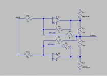
I recently replaced 2 modules on a ML1 for a friend (Phono and Line). I wanted to do something simple, OPA based otherwise it would have been better to redo the entire thing with something closer to the Vendetta. I made the circuit as follows:
An externally hosted image should be here but it was not working when we last tested it.
I tried AD797, AD743, LT1028, OPA134 and latter OPA627 give the best sounding results, all the others have a more pronounced SS or feedback…footprint (what you will). It is important to sink from the output around 5 to 7mA for that (carlosfm trick). It does not work equally with the others devices.
PMA said:Richard,
I agree with your description of sound of the opamps mentioned.
Pavel what about the the OPA827 sound ?
Richard,
I still do not know, I had 1 sample for measurement purposes. I believe to try them (sound) in a few months.
Thanks for reminding me your schematic.
I still do not know, I had 1 sample for measurement purposes. I believe to try them (sound) in a few months.
Thanks for reminding me your schematic.
jcx said:
it certainly appears the A/DSL driver op amps can't have measurable audio frequency crossover distortions if they do so well at MHz - is it then just a matter of power supply routing/partitioning to prevent the class B currents from coupling to the other circuitry?
The crossover is huge (even worse than you might think). Lots of feedback in this case. The power issue is Watts (1000's) at the head end. Either you meet the spec or no sales.
Scott,
From a technical pov, what's your take on that trick of putting an audio opamp output stage in class-A by loading it in one direction? That shifts the op point up to either the NPN or PNP output device, and this is also non-linear. Assuming that those output devices are carefully matched and biased to minimize xover distortion, would I measure less distortion when it is in class-A?
Jan Didden
Jan,
It's just to avoid low level high order xover thd (class B) worsen by feedback.
A comment on circuit presented post 4445:
The sound is significantly better than with the original modules except on complex symphony orchestra fortes, spatialization is also enhanced by the fet cap multipliers (crosstalk via supply rails).
Justcallmedad said:Jan, It's just to avoid low level high order xover thd (class B) worsen by feedback. [snip]
Yes, that's what everybody says. Did anybody ever check? 😉
Jan Didden
janneman said:Scott,
From a technical pov, what's your take on that trick of putting an audio opamp output stage in class-A by loading it in one direction? That shifts the op point up to either the NPN or PNP output device, and this is also non-linear. Assuming that those output devices are carefully matched and biased to minimize xover distortion, would I measure less distortion when it is in class-A?
Jan Didden
I've walked the current up and down and watched the spectrum. Sometimes its the n somtimes the p is better. It was more obvious in the old days with nasty lateral pnp's. Frankly modern complementary devices have so little measurable distortion that I don't quite see the point sometimes. For the record the audio community gets the fallout (at least around here) from whatever other industry is setting the specs. It's really rather silly to complain when 3.3V rail to rail battery powered parts pay the bills. A class A op-amp for 600 Ohm loads would be unmarketable.
A class A op-amp for 600 Ohm loads would be unmarketable.
And it was. BUF03, RIP.
Parasound pays my bills, but I don't change it, and I don't forget about Vendetta or CTC either. Quality is quality, at any price point.
Just thinking out loud, forgive me if this is stupid.
Can you sum two Op-Amps, whose outputs are biased so that the N stage is conducting in one and the P stage in the other? Seems you could use a moderate value summing resistor pair (few hundred Ohms?) because the way op-amps work only a small offset voltage will bias one half pretty much off. Since the two outputs will be nearly identical there will be only a small drop on the summing resistors. Take the feedback for both Op-Amps from the summing node this should return the output Z to near zero (watch out for compliance issues).
Parts count will be up, but at least no matching would be needed and any output stage crossover distortion should approach zero.
I don’t quite get the DSL reference. DSL is either multi-phase and multi amplitude or discrete frequency bins. In either case the signal is decoded into a digital bit stream. Crossover distortion should be decent but doesn’t need to be excellent. What am I missing?
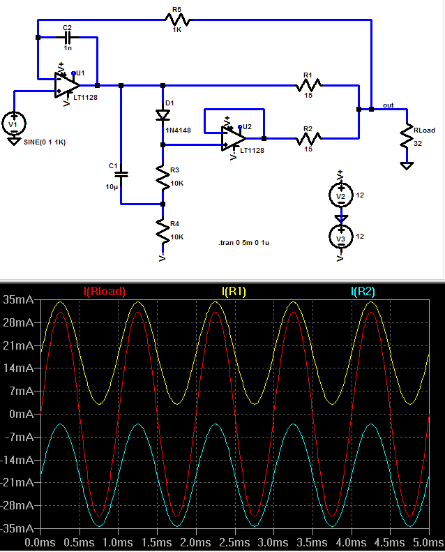
like this?
http://www.head-fi.org/forums/f6/ad8397-class-188758/index2.html#post2264079
up and down in that thread I show some more ideas and photo's of the amp internals - I will admit that stacking op amps in the "totem pole" output stage to double the Vswing does wander off into the too much complexity domain
DSL driver op amps compete directly on distortion specs at 100KHz+ driving low impedance transmission lines
the distortion has to be low to prevent IMD products from wiping local out adjacent channel S/N with the channel filling noise-like modulation used to cram the most bits into a given bandwidth
some appear to use several mA output stage bias so they could drive common audio input impedances wholly class A, they can have -100dB distortion specs into low Ohms at MHz which indicates to me that their output stages cannot be grossly nonlinear with deadbands or other artifacts
I am surprised to hear form Scott that some have poor open loop performance - maybe just the low quiescent current versions?
in any event the easiest way to apply them in a multiloop amp is with plenty of local feedback - since most are "faster" than some common audio transistors I would count the cfa output stage local feedback as nearly equivalent to the local feedback degeneration of an emitter follower
Exactly this I have proposed here. With normal line-level applications one almost always needs some isolation resistors on opamp outputs anyway, therefore there is seldom a true need for wrapping the feedback around the resistors. There are many other ways to have two or more outputs arranged in a push-pull fashion across amps, I've seen a few in this forum, just can't find them anymore.hermanv said:Just thinking out loud, forgive me if this is stupid.
Can you sum two Op-Amps, whose outputs are biased so that the N stage is conducting in one and the P stage in the other? Seems you could use a moderate value summing resistor pair (few hundred Ohms?) because the way op-amps work only a small offset voltage will bias one half pretty much off. Since the two outputs will be nearly identical there will be only a small drop on the summing resistors. Take the feedback for both Op-Amps from the summing node this should return the output Z to near zero (watch out for compliance issues).
Another tiny opamp trick I've used is normal class A biasing with a resistor or CCS, typically to the neg supply, combined with a second opamp in the same package (thus for duals) that inverts the signal of the first opamp and has the same total load conditions but is is not really in the signal path, being just a load balancing dummy. Then total power supply current in each individual rail is constant, which lessens the demands on the supply bypassing quite a bit. With a known load for the first opamp this constant current draw can be made virtually perfect. And the addtional cost and effort is really low, especially with the good old 5532 (which is much better than its reputation when used with optimized conditions).
Ah, I see one of those biasings pop up, thank jcx
- Klaus
I don't see a DC bias current on both output devices. As I described my idea, it won't work because the offset current simply flows through the totem pole resistor stack and not into or out of the Op-Amp output stage.
What's needed is a feedback for each Op-Amp (neg. and pos.) so that the output voltage stays near zero for no signal. The lion's share of the feedback would come from the summing node with a litle coming from the actual Op-amp output lead. This will make the voltage output near zero, forcing the offset current to flow into or out of the Op-Amps
What's needed is a feedback for each Op-Amp (neg. and pos.) so that the output voltage stays near zero for no signal. The lion's share of the feedback would come from the summing node with a litle coming from the actual Op-amp output lead. This will make the voltage output near zero, forcing the offset current to flow into or out of the Op-Amps
Attachments
jcx said:like this?
On second look (dinner break) I do see the DC bias. I guess I'm knee jerk opposed to the diode, have you run distortion analysis? Built it? listened to it?
In all fairness I've done none of those things with my post, just hobbyists trading ideas 🙂 🙂.
- Status
- Not open for further replies.
- Home
- Amplifiers
- Solid State
- John Curl's Blowtorch preamplifier