Yes, and the truth distills....baseless belief systems get revealed.I was noticing these differences before I came across Dan or anyone else for that matter.
Been looking for answers for over a yr now......a lot has come into focus during my quest.
I welcome the negative viewpoints just as well as the positive......you know yin/yang n’all 😉
Somewhere about there.....it's a feel thing between non melting the solder/non tinning the joint and scorching the flux and with LF solders the temp and time window is much narrower than Lead based solders.I got the .9 mm .....So if your melting point is 426 F. Where would you set the iron temp?
Like I said find some scrap boards and practice, you have the nouse to get the hang of it, the critical thing is to cleanse/deoxidise the tip immediately before each joint and be prepared to 'waste' solder in order to get a clean joint.
Dan.
you ought to consider that you are lead contaminated in biology and in listening, and that listening to lead whilst lead contaminated increases the biological effect of the lead in your physiology.....this statement will become more clear to you in time.
Fascinating ****. Be scared, be very scared.
Tin the wires, tin the posts and then sweat them together with the addition of suitable amount of new solder/flux.I was wondering the best attachment process for soldering the wire to the binding posts?
Dan.
Edit: Do the back of the posts accept Banana plugs ?.
Last edited:
Evidently there is much you do not understand about the effects of lead, counter intuitively this can be because of lack of lead in your physiology or because of abundance of lead in your physiology......if you are smart you can work out what this statement means.Fascinating ****. Be scared, be very scared.
Dan.
Last edited:
Looks like they might, but before I did that wouldn’t it be better just to solder a ring lug and tighten the nut onto it?
......do you have the same balls as Bob ?.
Dan.
That would be highly inappropriate.
For stuff like that you want to pick the thinnest part and solder to that. Not only will it take less heat but you will also heat up the whole thing less, which is a large concern since it is right on top of a PCB. It is easy to overheat something like this, and I would never put the PCB that close if I intended it to be a soldered connection after construction. The scoop on the back of those plugs is the solder cup style (the parts search/ordering term), and they are wrong side up if you want gravity on your side.
For stuff like that my butane iron is often not enough and I end up trying to use the torch instead. If your iron is not powerful enough it will conduct the heat throughout and then burn the PCB before it every get hot enough to solder. If you use the torch you really have to angle it away from the PCB as much as possible, preferably in the opposite direction and only touch the very end of the solder cup with the torch.
Soldering stuff like this is when it begins to require some skill. If you overheat it, it's thermal mass will continue to burn the PCB after you remove the iron and all you can do is watch (maybe use a can of freeze spray). And it will still be hot on subsequent attempts leading to more burning if you don't let it cool. You have to do a number of them before you have good judgement and a reliable process.
EDIT: A solder lug is a good idea, if purists don't demand a direct solder connection.
Last edited:
Yeah/Nah.....down the track the intention is to experiment with the RC network component types and maybe values which would be best connected to such ring lugs for soldering ease/ergonomics/electrical reasons.Looks like they might, but before I did that wouldn’t it be better just to solder a ring lug and tighten the nut onto it?
My intention is that the module output wires will be changed and either soldered directly to the back of the binding/banana posts or connected to banana plugs plugged into the back of the binding posts.
On second thoughts if you can get extra ring lugs then yes connect the module output to these ring lugs in addition to the RC networks ring lugs.
Dan.
Bob has big balls, your balls are small is that what you mean ?.That would be highly inappropriate.
Dan.
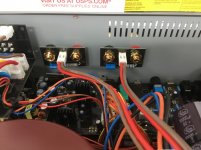
It looks like you could actually remove the PCB. The plastic grommets will melt even faster. Usually when I've seen terminals like this it's can't be reassembled after soldering the wires back. Been there, done that. If you can remove it in such a way that the soldered wires won't block reassembly then that is probably the best route. You don't want to melt those plastic grommets or singe the rear panel. It is reasonable to assume anything that touches the plugs will be damaged.
IMO. This makes sense.Looks like removal then solder would be best.....or better yet a quality ring lug?
On second thoughts if you can get extra ring lugs then yes connect the module output to these ring lugs in addition to the RC networks ring lugs.
Dan.
In addition to? There’s only one connection being changed right.....wire straight to binding post either by soldering or ring lug, right?.....The RC is still in play through the board.
Ain’t it like 3AM down under!?
Last edited:
I have just one advice, Bob. Do not believe much what is said. I am trying to stay polite as much as I can.
Well your the one that mentioned to directly connect the wires to binding posts!
Just trying to figure out the best way to do it? 😱
Just trying to figure out the best way to do it? 😱
Last edited:
Yes, this my intention and I suspect this final output 2 pin connector/RC network/binding post pcb is part of Bob's disappointment with the sound of his Hint amp and what I would remove if the amp were mine....I reckon this tiny little pcb is part of causing voicing that Bob does not like.It looks like you could actually remove the PCB. The plastic grommets will melt even faster. Usually when I've seen terminals like this it's can't be reassembled after soldering the wires back. Been there, done that. If you can remove it in such a way that the soldered wires won't block reassembly then that is probably the best route. You don't want to melt those plastic grommets or singe the rear panel. It is reasonable to assume anything that touches the plugs will be damaged.
Two ring lugs per binding post would be optimal perhaps...one for amp module connection and one for RC network connection....or RC directly connected to the binding posts and amp connected via ring lugs....or amp module and RC network connected in the same solder joints in the back of the binding posts.....there is room for experiment.
Dan.
Uh huh, so why should anybody believe your statement ?.I have just one advice, Bob. Do not believe much what is said. I am trying to stay polite as much as I can.
Or perhaps you might like to divulge all about your belief systems ?.
Dan.
- Status
- Not open for further replies.
- Home
- Member Areas
- The Lounge
- John Curl's Blowtorch preamplifier part III