Phase angle at impedance peaks is zero, load looks as pure resistive. So at impedance peaks is back EMF zero. 😉You lower the driver resonance Z peaks. Those peaks, especially at the low frequencies cause the most back EMF. Limited Z of reson peaks limits/lowers the back emf.
Thx=RNMarsh
You are assuming Joe understands "reactive". Based on his shyness in using the Ohm's law, I would think not.I missed that, yet he talks about reactive current so I remain skeptical that there is more going on here.
I think we need to dump the evil dB as well.I'm trying to understand this and make sense of it, especially the part I put in bold.
Can anyone help? Am I trying to read too much into a few seemingly contradictory sentences?
Now how would an impedance peak actually exist, unless it was putting out some feedback voltage generated by the resonance? How does the amp 'know' to not supply more current than the impedance suggests?
Finally, how do we make a VOLTAGE AMPLIFIER? There are two approaches: First, you can generate a low impedance within the amplifier without Global negative feedback. You do this with triode amps because the PLATE RESISTANCES of a triode tube are so low and go even lower after being stepped down by the output transformer. Second, you can apply negative feedback, which is limited to about 20dB for practical reasons for tubes, but 60 or more dB is practical with solid state. You can combine lots of negative feedback with also using lots of emitter followers in a string, to create a low output resistance, even before global negative feedback is applied and the two will create even lower output resistance. However, there are potential problems.
Some amps don't even bother with an intrinsically low resistance (without feedback) but simply make a high output impedance output and rely on negative feedback to lower it to acceptable levels. Both pentode output vacuum tube amps and some collector output solid state power amps do this.
What happens then? What we can get is IIM distortion, because the poor global negative feedback loop can be overworked (you know overloaded, overdriven, and making lots of input stage distortion) and giving you poor performance even when you think everything is OK, because you tested the amp with a resistor load, or even a static capacitor or inductor. Now we separate the good amps from the marginal ones!
What can I say. Never asked for any. 😕Which fidelity information on which component were you looking for?...
"If you build it, they will come." If you search for it, you will find.What can I say. Never asked for any. 😕
yes... off zero on either side will generate plenty of back emf. I mentioned this already... a cap suitably placed in the feedback will generate the 90 degrees need to place you back at reso freq for max effect.Phase angle at impedance peaks is zero, load looks as pure resistive. So at impedance peaks is back EMF zero. 😉
THx-RNMarsh
🙂 😎Thanks and yes I know.....BUT the perfect voltage amplifier should not be fazed whatsoever, it must be that my amplifier is not so perfect as the DF spec would lead me to believe.
Yes.....
THx-RNMarsh
...using 'inappropriate' descriptions of what I was finding in the CAP DA test that Scott Wurcer invented (at least he contributed the INAMP). He told me that I was no 'engineer' and therefore I could not know what I am talking about and he did not want to discuss with me further. Oh well, we sited him anyway in our article, because it was the professional thing to do.
That just made my day! 😀
I had seen this before in 1977, when Matti Otala (Dr in engineering, and full professor at times) got criticized by Dr. Cherry, for using the word 'overload', instead of 'overdrive'. Oh joy! '-) Cherry also did not like the term (TIM) but wanted to rename the distortion 'slope distortion'. Of course, where was he when he wrote a nearly 1000 page book on amplifier design in the late 60's, and did not mention any sort of 'rate related' distortions in his book? And so it goes.
Never met Otala, but I've met Per Abrahamsen who collaborated with him and we have talked at length. Never had a language problem!
I do remember that it was suggested to me, if I should move to Canberra, that I might get a job at the ANU. People can Google what it is. But with those guys never had a language problem!
I was told emphatically that only one thing counted, RESULTS!
Yep, if you could come up with the goods, you got respect and if you could communicate effectively IDEAS, in that case language would not be problem!
Whatever happened to that American "can-do" attitude?
I won't follow every nit-pick and criticism printed here, because most are trivial and virtually meaningless. However, whether Joe has done something useful, or not, is not for me to determine, nor any of the rest of you, without seriously trying it first.
It's not really that hard. And you can test it in software already available:
In fact, John Kreskovky (some of the guys here would know about him) saw earlier posts that I could use SoundEasy to model what I am talking about and did not deny that it did what it did. JK was hardly my stooge, in fact I don't think he was anybody's stooge.
So Bohdan in writing/programming SoundEasy clearly has been using current EE and mathematics.
So anybody can model what I have done, by getting their hands on SoundEasy and you don't even have to build it physically.
I have modelled it and I have built it physically, many times over. I am not the one hiding his head in sand.
Hi Joe,
-Chris
Well ... it is helpful if you can explain how you got there. Using a different language isn't going to help anyone.I was told emphatically that only one thing counted, RESULTS!
-Chris
Phase angle at impedance peaks is zero, load looks as pure resistive. So at impedance peaks is back EMF zero. 😉
No, back EMF is maximum at resonance peaks. It is just that there is no phase angle at that particular point. Left and right of the resonance peak there are. EMF is just the voltage produced by the voice coil moving through the magnetic field. There is always EMF generated when a speaker produces sound, not just at resonance. It is quite easy to calculate how much Voltage Generated in a Moving Wire
Never seen an amplifier that could not cope with speaker current around resonance being out of phase with voltage. Don't forget that around resonance, impedance is highest because of the generated EMF and so the load becomes easier on the amp, not more difficult. Watt for Watt, you can produce the most acoustic power out of a loudspeaker at resonance. Thanks to back EMF, loudspeakers are linear above resonance under voltage drive.
Last edited:
I do remember that it was suggested to me, if I should move to Canberra, that I might get a job at the ANU. People can Google what it is. But with those guys never had a language problem!
I was told emphatically that only one thing counted, RESULTS!
I hope the ANU suggestion was not made tongue-in-cheek...
Because you mentioned it, can you point me and everybody else to your tangible results? I see a lot of talk and name droppings but little to nothing in results: models, prototypes, equations (beyond F=BiL), measurements, simulations, controlled listening tests, reviews, anything that would support your idea(s) beyond volatile words.
That's even worse, it's the LOGARITHM of a ratio!I think we need to dump the evil dB as well.
I recall the AES shirts printed every year for the newsgroup rec.audio.pro - I got the one that says "My tapedeck can beat up your digital audio workstation."
One I did NOT get had a bunch of abbreviations:
dBSPL
dBm
dBu
dBV
dBv
dBWTF?
Now, what is damping factor? It is simply the effective output impedance of the amplifier at some nominal frequency, let's say 1KHz, divided into 8ohms. That is it, so far as I know.
That's it alright.
It's just a number.
Just dividing two numbers mean nothing. But when they are in series and conducting the same current, how does it make sense. It's in series, should that not raise an EE alarm?
Now, for the other side: How important is damping factor (DF), the number?
Mostly useless, except as an advertising point.
Now there is something that we ALL should agree upon.
John, did you read what I said before, the F. Langford-Smith was the first to coine DF only to disavow it for the very same reasons I have pointed out.
If ever there was proof that advertising works, it is cigarettes and damping factor! 😀😀😀
But is a DF of 100, better than a DF of 10? Maybe. Yet it can be shown that the relatively high series resistance of the voice coils completely compromises any high damping factor to almost meaningless in a real situation, even if it might change the overall frequency response of the speaker just a little. I would presume that Small, and others were taking this into account.
[my underlining]
BINGO!
Yes, Small did. And it is embedded in this equation:
Qes = (2Pi*Fs*Mms*Re)/(Bl^2)
[Qes=ElectricalDamping, Fs=FreeAirResonance, Mms=EffectiveMovingMass, Re=TotalSeriesDCR, Bl=MotorForce]
This equation makes damping factor a mockery (is that not a good way to describe most audio advertsing?), because Re is a POSITIVE number and it would need to be negative. Not a good place to go, we agree.
Also, that Re (voice coil), for any current to go back into the amplifier via the amp's output impedance has to go through Re first. Talk straight, the Re is a current limiter and if such current was generated, the heat would be dissipated in the voice coil first.
This was also the reason that Langford-Smith rejected his own invention in Wireless World 'Answers' section.
Now is a modestly high DF always the best? No. I have experimented with a DF of 1, on a particular direct radiator acoustic suspension speaker and found it sounded best. It was unfortunate, because the added series resistor, about 3.3 ohms threw away significant power, but when 2 or more of us heard it, it was obvious that the series resistor should remain.
Small suggested that I add resistors with overdamped speakers, even gave me all these computer printouts for a driver I had bought.
At European Triode Festival 2017, Menno vander Veen brought a modified Putzey Class D amplifier (I think it was the NC generation) and it had multiple output impedances, zero, I think 6 Ohm and I definitely remember the highest was 18 Ohm. A bunch of people in the room, they all preferred when the amplifier was not a voltage source. Menno preferred 18 Ohm himself.
What was apparent is that there is a real interest now in this topic. People like JC Morrison and Kurt Steffensen and Menno of course. Heaps more.
Hey guys: Get your resistors out!
Just kidding.
Also, there is NEGATIVE DAMPING FACTOR, that will partially remove the effect of the voice coil resistance. The problem with this is if you use too much, then then you will get oscillation, so it is tricky.
That's a fact. John, look at the above equation, what you said about negative impedance and - dare I use the "cancel" word? Yes, you have to cancel out the Re or at least part of it.
Positive: The damping gets worse.
Negative: The damping gets better, but I wouldn't try it.
So what I said is true, whether my way of saying it is acceptable or not, but it is an EE fact that the amplifier's output impedance can only make damping WORSE because it is a POSITIVE number.
Hence an amplifier cannot add damping. It cannot lower Re.
EE 100% correct!
Last edited:
The question still remains that paralleling at the speaker with a R (50-75 Ohms) makes an audible difference compared to no added R.No, back EMF is maximum at resonance peaks.
Never seen an amplifier that could not cope with speaker current around resonance being out of phase with voltage. Don't forget that around resonance, impedance is highest because of the generated EMF and so the load becomes easier on the amp, not more difficult. Watt for Watt, you can produce the most acoustic power out of a loudspeaker at resonance. Thanks to back EMF, loudspeakers are linear above resonance under voltage drive.
Why?
THx-RNMarsh
No, back EMF is maximum at resonance peaks. It is just that there is no phase angle at that particular point. Left and right of the resonance peak there are. EMF is just the voltage produced by the voice coil moving through the magnetic field. There is always EMF generated when a speaker produces sound, not just at resonance. It is quite easy to calculate how much Voltage Generated in a Moving Wire
In my work it is rather easy to tell the difference between the biamplified low and high frequency loudspeaker components. As the high frequency units are generally compression drivers into horns the measured impedance fluctuates wildly in real time with no program signal applied. This is due to the back EMF from the wind or even noise.
As the high frequency section runs around 30% efficient and the test signal runs around 125 milliwatt the apparent swings in impedance can exceed 3:1. The low frequency section usually having an efficiency of under 2% rarely shows any such variance.
We do not triamplify as the woofer has to work hard due to the energy content in the program material. The high frequency section has to overcome atmospheric losses and the midrange, often horn loaded just coasts. The power distribution is often 500 watts for the woofer, 300 watts for the high frequency driver and 5 watts for the midrange driver! Funny how 20 dB of atmospheric losses tilt power levels. BTY rarely is it possible to get high frequencies above 10,000 hertz to the seating.
The question still remains that paralleling at the speaker with a R (50-75 Ohms) makes an audible difference compared to no added R.
Why?
THx-RNMarsh
You know very well that we are speculating about possible HF EMI induced voltages and reflections attenuation in such case. Amp output impedance is not well defined in >= 10MHz range and the speaker cable HF conditions are undefined at both ends, which is a bit improved if you place a parallel resistor of 50 - 300 ohms at the cable end. However, this has not much in common with the audio frequency amplifier DF discussed.
Sorry, both of you are incorrect.Phase angle at impedance peaks is zero, load looks as pure resistive. So at impedance peaks is back EMF zero. 😉
No, back EMF is maximum at resonance peaks. It is just that there is no phase angle at that particular point. Left and right of the resonance peak there are. EMF is just the voltage produced by the voice coil moving through the magnetic field. There is always EMF generated when a speaker produces sound, not just at resonance. It is quite easy to calculate how much Voltage Generated in a Moving Wire
Never seen an amplifier that could not cope with speaker current around resonance being out of phase with voltage. Don't forget that around resonance, impedance is highest because of the generated EMF and so the load becomes easier on the amp, not more difficult. Watt for Watt, you can produce the most acoustic power out of a loudspeaker at resonance. Thanks to back EMF, loudspeakers are linear above resonance under voltage drive.
Back-EM-"Force" is IMO a dangerous term as it denotes a voltage(!) and not a mechanical force, therefore it often get's mixed up with the mechnical force which is created when this Microphonic Voltage (preferred term) has some resistance (driver's Re + any external source resistance) to work upon, which converts it into a current which in turn creates a mechanical force on the cone (which happens to be in opposite direction than the force applied via some current to get the cone moving in the first place).
Summed up: Back-EMF is an exact measure of the velocity of the cone. With the SPL (==acceleration) being a 2nd order highpass, velocity then is a 2nd order bandpass function (one integration). Which means it is highest at the corner frequency, no matter how that corner is established.
Mechanical Resonance has nothing to do with it. Resonance has effect on the current needed to sustain motion at that frequency. At resonance, current is lowest because the cone is already quite moving like we want it to move with little current "refill" needed to keep it moving. OTOH, when swapping the phase of an exitation at resonance suddenly, a large current is needed to stop the sympathetic movement of the cone and revert it properly if we want the cone movement to follow the exitation voltage signal.
It's all in the following most basic equation:
At any point in time
e(t) = k*v(t) + Ze*i(t),
e(t) is the terminal voltage, v(t) is the cone velocity, k is some constant, i(t) is voice coil current, Ze is the static VC impedance (== Re at low freq).
What it means is this: To induce any change in motion the amp must always apply a voltage corresponding to the microphonic voltage *plus* the voltage required to produce the needed current through Ze. Around resonance, this required current is smaller than at other points which yields a higher terminal impedance e(t)/i(t) (now being sinusodial functions).
It also shows that the driver has more intrinsic local feedback (velocity self-control) when Ze is getting lower and/or microphonic voltage is getting higher (actually, it's not Ze but rather Ze/(BL)² which determines both the effectiveness of the motor force and the microphonic voltage). A small difference between applied voltage and self-measured velocity is going to produce a large correction current until the microphonic voltage (velocity) matches the input signal.
<snip>
Of course it's strange to you when someone asks about listening test (WRT damping factor) when you were trying to spread FUD once again.
Mhm, that is interesting and raises several questions:
-) where was the FUD?
-) what should be the independent variable in the listening test, DF ? ´which loudspeaker(s) would you recommend?
-) which kind of result would corrobate your "FUD assertion?
Of course seems that way to you. After all, you are in audio business and your objective here is to help your business.
Really?
But anyway, Feynman was not and his advice (you know the easiest one to fool .........) and his remarks were spot on wrt what science should be about.
Try it, there is nothing to loose...... 😉
You know very well that we are speculating about possible HF EMI induced voltages and reflections attenuation in such case.
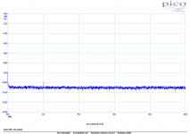
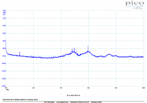
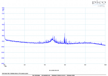
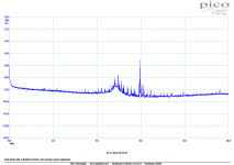
I have numerous measurements of HF EMI induced voltage via a speaker cable into amplifier terminals, with different cables, amplifiers and terminations. This is something I consider my know how and will leave to our renowned designers present here to make their own research.
-) what should be the independent variable in the listening test, DF ?
Output impedance, change is realized by a series resistor, level is easy to keep the same. However, this affects frequency response, in the same way as higher output impedance of tube amplifiers.
Attachments
Manipulating low FR with damping seems a very crude/hit and miss way of trying to extend it.
- Status
- Not open for further replies.
- Home
- Member Areas
- The Lounge
- John Curl's Blowtorch preamplifier part III