And in the decade I floated this, PMA is the only one to actually put the effort into proving it correct or incorrect.
Really?

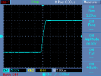
Ahem... rise time. Your preamp has about 500KHz bandwidth. Right at the limit of the AM radio band. Long wave stations in Europe (if any left) will go through 😀.If I care or do not care about slew rate can be seen from a measurement of one of my preamplifiers
Your slew rate is likely much higher than the max derivative of this signal. And the derivative of a slewing signal is constant, doesn't peak.
Sorry, I'll be clearer. The step/settling test is looking for a difference in a timeframe that your rise time falls within. From my military test experience, they always require the test capability be at least ten times better than the entity being tested. For example, to test the TRR of a diode with an expected value of 15 nanoseconds, using a test fixture waveform that changes value in 100 will not be acceptable.I am really not sure what you mean when saying that "I should follow all the constraints (slew rate)". Sounds to me that I am supposed not to know what slew rate is and when it is important. <snip>
To test settling times at the 1 uSec level, use of a signal that takes 3 will not show the entity.
To be more accurate, you should be in the 200 to 500 nSec range, and your measure should be from the say, 50% level of the input waveform to perhaps 90% of the output waveform. 90% of course is a debatable entity.
I meant by doing the exact step test as specified.Really?
Sorry.
Jn
Sorry, I'll be clearer. The step/settling test is looking for a difference in a timeframe that your rise time falls within. From my military test experience, they always require the test capability be at least ten times better than the entity being tested. For example, to test the TRR of a diode with an expected value of 15 nanoseconds, using a test fixture waveform that changes value in 100 will not be acceptable.
I agree. Stimulus is at least 10x faster than the response.
I have also shown a zip cord response here driven from fast ns rise time generator. Of course it shown reflections, but I am saying such reflections are never excitated when cable is connected in an audio system as a speaker cable. Still not sure what we are trying to get.
- Cable wave reflections can be easily simulated and cable model is supposed as non-ideal, lossy line
- step response of the cable model with speakers including crossover can be easily simulated
- Simple RLC model or distributed elements model can be easily simulated
- Real time delays and phase shifts when cable is loaded with a speaker model can be easily simulated.
I am sure that not only me, but many other capable engineers in this thread have already done it. This thread has many smart participants. So if there were any hidden species, I am sure they would be discovered.
No. That constant Z is the RF characteristic impedance of the cable. At lower frequencies you measure a different value, typically higher, reactive and frequency-dependent. This too is the characteristic impedance at that frequency.
of course there is an impedance at any freq and YOU may call it what you wish. Characteristic cable Z is as I described.
THx-RNMarsh
Although it can be represented in terms of inductors, capacitors and resistors, characteristic impedance is a complex number that is highly dependent on the frequency of the applied signal. Zo is not a function of the cable length. At high frequencies (> 100kHz), the characteristic impedance is almost purely resistive.
Last edited:
I don't like the gauge, otherwise it' no worse than zip. If one does what I did, I would be afraid of the capacitance.
Jn
So - setting gauge apart (if it's short it won't be significant) - it's worse because of the proximity of the pairs? Ie, your paralleled zips need to be well separated?
Though, as was observed earlier, in a stable amp the capacitance shouldn't be a big issue.
I only asked as it seemed a good practical possibility for short runs - though mine are only 20cm so wet string would almost work 🙂
Two conditions were ignored.
1. Your rise time is long or longer than the entity to be measured.
I may be wrong here, but I think this is exactly the point of contention between you guys.
Pavel used a realistic rise time for an audio amp output.
If the signal rise time is always longer than the relevant "entity" - then does it matter?
I think that's what is being said. Don't shoot the messenger... 😀
My guess is yes.jneutron said:So the question remains, will it be possible to get accurate coupler results even with impedances in place of resistances?
Don't know.And to what degree will the coupler output amplitudes be affected by the complex impedance of the cables at low frequencies.
That may be specmanship. Having transformers etc. within the design so it could work at 10kHz at 50R does not mean that 10kHz at 50R is a likely or useful thing to do. You would need a cable with quite high inductance, which may mean a lot of interference pickup too so such a cable might be of no practical use.The RF people, even HP claim their devices as good (IIRC) well down below 10 kHz, are they missing something?
With a short cable (which his cables are at audio frequencies) the cable does not do very much. He is probably measuring the mismatch between his bridge and the terminating impedance, even though he thinks he is measuring the cable. In addition, it is possible that he is calculating the result of his experiment using the same flawed understanding as he uses to calculate the theoretical result. Thus theory and experiment could match while both are wrong. As I have said, I see no clear evidence that he is comfortable doing complex arithmetic. There are several places in the article where he could make this clear but in each case he does not, by apparently treating all impedances and reflection coefficients as real when they will actually be complex.Within his article, at 10 kHz, he shows the results of the supra reflecting with matched load, open load, and shorted. In all three cases they match exactly the prediction of reflection coefficient. No reflection matched, negative shorted, positive open, and in phase. If the complex impedance of the cable didn't trash his measured outcome, why?
No. Saying 'characteristic impedance' when what is meant is 'high frequency characteristic impedance' is a common shorthand, but it leads to confusion unless the domain under discussion is entirely high frequency. There are lots of people who think that Z0 is defined to be sqrt(L/C). It is not. It is defined to be either the impedance at the input of an infinite cable, or the impedance which correctly terminates a finite cable; these two definitions are equivalent. It just happens to be the case that at high frequencies a sufficiently good approximation is sqrt(L/C).RNMarsh said:of course there is an impedance at any freq and YOU may call it what you wish. Characteristic cable Z is as I described.
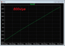
Attached the virtual SR (10%-90%, passive filters removed) of my last amp in progress. Yes, it is a CFA: I like, for the treble that my amps have time to take a little cigarette break between two level changes ;-)Yes, it is a little bit below the SR limit, it was difficult to get because the preamp would need to overdriven.
Attached is a slew rate of another preamp.
Attachments
Nominal impedance - The nominal value of the characteristic impedance of a cable or other form of transmission line.No. Saying 'characteristic impedance' when what is meant is 'high frequency characteristic impedance' is a common shorthand, but it leads to confusion unless the domain under discussion is entirely high frequency. There are lots of people who think that Z0 is defined to be sqrt(L/C). It is not. It is defined to be either the impedance at the input of an infinite cable, or the impedance which correctly terminates a finite cable; these two definitions are equivalent. It just happens to be the case that at high frequencies a sufficiently good approximation is sqrt(L/C).
Dan.
The biggest problem with high slew rate amps is the pcb artwork.It's fairly easy to deal with high slew rate op-amps as the surface taken by the circuit is very small, not the same with high power amps.The good power amps with high slew rate are actually sounding darker and extremely boring, like having less highs while they actually are less zingy.
Propagation by diffusion only would be limited by the drift velocity I assume (I might be wrong).
I know one theoretical physicist who left that field for medical physics. He said the reason he left was because it had become acceptable to essentially model by curve-fitting: If a model gives the right answer, then no matter if it actually represents the underlying process.
Isn't it a very useful tool, modelling of behaviour of light for exampleIf a model gives the right answer, then no matter if it actually represents the underlying process.
Yes, one of the issues. It is possible to design a well working high SR power amplifier, but it is useless for audio. Again, it is easy to calculate maximum possible SR of the audio signal and to build the amp with at least 10x higher slew rate limit. I have built a 2x300W power amp with SR = 120V/us. However, it is really useless. It is like all the discussions here. Hunting resistor distortion, cable delays, highest SR - and then we see that the real issue was an amp prone to oscillations under certain signal and load condition. I have to say that about 17 years ago, when the part I of this thread was started, I could learn something here. Unfortunately, during last 10 years, there is nothing like that. But I am afraid that the debate may bring a lot of confusion to the newcomers, which is probably the only outcome.
If I go into a room where five navy seals have just synchronized their watches, and then I ask all five what time it is, I can think it must be right because all 5 have the same time.I agree. Stimulus is at least 10x faster than the response.
I have also shown a zip cord response here driven from fast ns rise time generator. Of course it shown reflections, but I am saying such reflections are never excitated when cable is connected in an audio system as a speaker cable. Still not sure what we are trying to get.
- Cable wave reflections can be easily simulated and cable model is supposed as non-ideal, lossy line
- step response of the cable model with speakers including crossover can be easily simulated
- Simple RLC model or distributed elements model can be easily simulated
- Real time delays and phase shifts when cable is loaded with a speaker model can be easily simulated.
I am sure that not only me, but many other capable engineers in this thread have already done it. This thread has many smart participants. So if there were any hidden species, I am sure they would be discovered.
If all engineers are taught the exact same thing, does that mean that it is correct? As DF96 knows (given a PhD), it is always important to consider the possibility of a paradigm shift.
Just as it is very important to not take a theory, postulate, or even a testable entity presented at truth. It must be reproduceable and validated to be accepted.
If I wanted this or my biwire analysis accepted blindly, I would post it all over at Cable Asylum where I would then be considered a cable GOD, and be Duster's BFF..
Your preamp and amp waveforms are awesome, very nice work.
The capacitance of each pair adds when they are paralleled as pairs. I can see unknowing individuals simply taking 6 cat5e cables, paralleling all 24 pairs, and connecting them to a speaker with no zobel and a fast amp, releasing the smoke. One cable paired up doesn't have so much capacitance.So - setting gauge apart (if it's short it won't be significant) - it's worse because of the proximity of the pairs? Ie, your paralleled zips need to be well separated?
Though, as was observed earlier, in a stable amp the capacitance shouldn't be a big issue.
I only asked as it seemed a good practical possibility for short runs - though mine are only 20cm so wet string would almost work 🙂
I may be wrong here, but I think this is exactly the point of contention between you guys.
Pavel used a realistic rise time for an audio amp output.
If the signal rise time is always longer than the relevant "entity" - then does it matter?
I think that's what is being said. Don't shoot the messenger... 😀
I concur, Pavel is using very reasonable and realistic rise times when it comes to human frequency capabilities.
The disconnect is because ITD numbers are exceptionally faster than the bandwidth of human hearing w/r to frequency response.. Nobody has come up with a reasonable method of trying to ascertain nor measure such an entity, hence my efforts at attacking the power delivery method, the conversion to acoustic pressure thingy, and whether or not it is possible for the two to interact in such a way as to alter the signal to exceed human levels of ITD..
Stating that an amplifier is "fast enough" does indeed cover anything the ears can hear in a monophonic situation, but the stereo condition adds the ITD concern. The expectation that an amplifier has sufficient bandwidth to assure the two stereo signals acoustically maintain a rigid control of ITD may not be correct.
There is expected to be confusion, discussion, disagreement until all are on the same page with respect to how to address ITD timing levels. At this point in time, understanding of it and the ramifications of it on system design are just beginning to be discussed.
jn
Last edited:
It's it a very useful tool, modelling of behaviour of light for example
Okay, but is it Applied Physics or Theoretical Physics?
Too much theorising and not enough application?It is like all the discussions here.
WHAT IS WRONG WITH YOU!!!! 😀Okay, but is it Applied Physics or Theoretical Physics?
There is High energy physics, neutron physics, condensed matter physics...
And each has experimental and theoretical. six categories...
And, they ALL look down their noses at the others...😉
jn
Re ITD discrepancy, it wouldn't so much shift the image as make it unstable since it's the time of arrival of the sound that is detected not once if is a steady state, so perceptually it would wobble about
- Status
- Not open for further replies.
- Home
- Member Areas
- The Lounge
- John Curl's Blowtorch preamplifier part III