At 1kHz with the Supra cable he would need a bridge calibrated for a characteristic impedance of 93.6 -j79.2. Possible, but unlikely given that he simply gives Z0 as 114.6?jneutron said:The answer is, he made his own bridge.
I see no evidence in the article that he is comfortable with complex arithmetic, and there is some evidence that he is not. For example, on page 7 he talks about amplitude and polarity of reflections when he should be talking about amplitude and phase. He says that a particular reflection coefficient is negative when in fact it will be complex. Hence there is reason to doubt his results where they depend on a correct understanding of complex numbers.
So which switch position should he use for a 93.6-j79.2 cable?jneutron said:He then goes on at length describing a two transformer directional coupler. He also used a two gang switch to select the measurement impedance, with choices of 15, 25, 30, 39, 50, 62, 75, and 100 ohms.
JN, you have me all wrong, I am actually completely in the objective camp, I study theories but that said I do not automatically believe theories.
That I am in the objective camp also means that I recognise measurements and that all measurements are useful, however I also recognise that the usual measurements do not quantify all subtle sound qualities, especially subtle dynamics qualities and behaviours.
I do not believe in or respect the 'fashionista/wank fest' ultra high-end part of audio industry, but I do respect good and clever engineering be it in pro-audio, hi-end, mid-fi or consumer level etc or even a mousetrap or clothes peg.
My quest is for properly good sound from economical standard audio equipment and I have achieved this by method of addition of 'filters' to existing equipment.
My filter technique gives such systems a little help in the real world, and serves to reinforce that long accepted audio quality standards are indeed valid.
I could spend my efforts designing novel circuits or optimal layouts but this would be wasted energy and merely reinventing wheels when the current 'wheels' are plenty good enough when filtered and interfacing correctly with the real world.
That I do not have proofs of the physics of operation of this filtering method does not discount the fact of their modification of system behaviours.
This filtering is not voodoo, this is real world behaviours that will have deep rooted explanations, just that the physicists that I have demonstrated to did not have explanation either.
Remember, if we all knew all of physics already, why would we bother to construct and maintain costly projects like accelerator or gravity wave projects.
We have plenty of observations of electric and magnetic properties of matter and space and we can harness these properties, however the fact is we still don't have all the explanations of how these fundamental attributes are derived from well, nothing.
My research is ultimately for the benefit of my children and your children alike, I find it sad that you should hate anybody or anything.
Dan.
I think it would be quite difficult to design and build a directional bridge that would be able to measure reliably reflections at 10kHz. Just try to search available products. And review the principles.
At 1kHz with the Supra cable he would need a bridge calibrated for a characteristic impedance of 93.6 -j79.2. Possible, but unlikely given that he simply gives Z0 as 114.6?
I see no evidence in the article that he is comfortable with complex arithmetic, and there is some evidence that he is not. For example, on page 7 he talks about amplitude and polarity of reflections when he should be talking about amplitude and phase. He says that a particular reflection coefficient is negative when in fact it will be complex. Hence there is reason to doubt his results where they depend on a correct understanding of complex numbers.
I think you are nitpicking (unlike me of course🙄 ). When a delay shows up with this essentially zero time line length, either positive or negative coefficients will be complex, resistive only has no delay. I have no problem with him loosely calling a reflection coeff as negeative if the bulk of it is indeed negative. As a first principle article set, it ain't too bad, and none of it is blatenly incorrect.
He did discuss the issue of not matching the cable exactly in appendix 2, again no link to the appendix..sigh. He allows a coupler resistance to cable mismatch of 1.2:1.
jn
Even if we admit existence of 10kHz reflections on a 4.9m cable as Bateman describes (and I not only doubt it but think it is impossible), he speaks about 40% amplitude of the reflected wave compared to forward wave. If it was 40%, it should be easily visible in an oscilloscope test. So, until somebody repeats the experiment in a trusted setup and gets the same result, I am saying that the article measurements are wrong.
Your practical input is valued here
Measurements are good, of course. On the other hand, some of what JN has talked about in the past has been interesting and informative. For that reason I am willing to hear him out now. However, I would agree that the claims seem to go against common sense in terms of short times and high frequencies, and for that reason could use some more detailed explanation than we have had so far in the present discussion. Perhaps a summary of some of the past explanations would be helpful now. JN, are you assuming everyone is familiar with your past comments on speaker cables, eddy currents, Bessel functions, etc.?
You are kidding, right? Given the flavor of my post, how could you possibly misconstrue my humor???I find it sad that you should hate anybody or anything.
Dan.
I think it would be quite difficult to design and build a directional bridge that would be able to measure reliably reflections at 10kHz. Just try to search available products. And review the principles.
Apparently Cyril overcame that difficulty and made it and tested it's performance. And, compared the 50 ohm performance to the HP he owned.
I know I could not design one, but my difficulty in that respect doesn't mean others cannot do it. If you find it too difficult, hey, you're human and welcome to the club.
I considered storing antimatter in a magnetic confinement bottle to be impossible, until some smart guys did it.. And my reaction then was...who thinks of this stuff?
jn
He was saying 40% amplitude of the reflected wave at 10kHz. Why don't we see it with another, verified method like oscilloscope measurements? Maybe just for the reason that CB measurement is completely wrong?
Even if we admit existence of 10kHz reflections on a 4.9m cable as Bateman describes (and I not only doubt it but think it is impossible), he speaks about 40% amplitude of the reflected wave compared to forward wave. If it was 40%, it should be easily visible in an oscilloscope test. So, until somebody repeats the experiment in a trusted setup and gets the same result, I am saying that the article measurements are wrong.
How in the world would we look on an oscope to see that? Surely you jest.
So you are saying that if a cable is carrying energy in two directions, if your scope doesn't show each component individually you say it's wrong?
Wow, not sure what to make of that. One of the first things I learned was the fact that two waves can travel in opposite directions on the same cable. A simple single point scope connection cannot tell you which direction, only the summation voltage at that point. This is one of those fundamental things.
Your difficulty seems to be that if they temporally overlap too much, they can't exist..whoa...😱
jn
hello..... T,
My question to my self was this --- we test into resistive loads for FR and THD/IM. Then we listen with a speaker connected. We could test with a speaker attached, I suppose. But there is no standard speaker. What would it sound like if the same speaker was like a resistor which could reproduce sound? Does the particular power amp sound different loaded as an almost pure R than a reactive speaker?
In other words, do these 2 Z curves sound different on any particular PA?
View attachment 759686
Using an RC network only flattens some of the freq range. The shunt/parallel R flattens the whole range.
I didnt say this much about it because it is so easy for anyone to try and then listen.
THx-RNMarsh
You mean it as test, not permanent solution, I hope, otherwise you waste a lot of amp power even on 50R resistor.
BR Damir
There is only one voltage value at a given time at a given place of the cable. This value is superimposed from traveling waves in the cable. Same way we can see reflections on scope screen for fast signals, we would see it for 10 kHz. If it existed. As it doesn't exist, it is a chimaera.
I am looking for evidence of the necessary understanding to correctly interpret the raw data he gets from his instruments. I do not see it. I may be wrong.jneutron said:I think you are nitpicking
So what is the mismatch between 100R (his nearest switch position) and 93.6 -j79.2? Somewhat greater than 1.2:1, I think. Let us take a short cable with a characteristic impedance of 93.6-j79.2, and terminate it with 100R. His bridge will tell us that there is virtually no reflection. In fact the reflection coefficient will have a magnitude of 0.38 with an angle of -72 deg. What his bridge is actually doing is telling us about the mismatch between the bridge calibration impedance and the cable termination impedance, very slightly modified by the LCR of the cable.He allows a coupler resistance to cable mismatch of 1.2:1.
How likely is it that new physics will turn up when someone puts gloop or flooby dust around an audio cable? New physics which has eluded CERN, Fermilab, LIGO etc.? New physics to be discovered not in the laboratory part of the site but in the audio system in the staff canteen?Max Headroom said:Remember, if we all knew all of physics already, why would we bother to construct and maintain costly projects like accelerator or gravity wave projects.
What his bridge is actually doing is telling us about the mismatch between the bridge calibration impedance and the cable termination impedance, very slightly modified by the LCR of the cable.

-rnm
-rnm
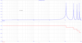
JN asked how can I see it on the scope. Just according to the definition, sinus sweep and voltage measurement. As simulated for 4m of cable, inp from 0ohm, output 1Mohm load. Simulated, however scope shows the same. First signs of "sub/wavelength" effects are above 1MHz.
Attachments
...it will exactly match the lumped LCR element analysis.
As it should in the steady state.
I don't have explanation for a bunch of interesting effects, and neither do the physics profs that I have demonstrated to.How likely is it that new physics will turn up when someone puts gloop or flooby dust around an audio cable? New physics which has eluded CERN, Fermilab, LIGO etc.? New physics to be discovered not in the laboratory part of the site but in the audio system in the staff canteen?
It would seem that modern physics ought to have common explanation but then if it did surely this principle would be in wide use, this is odd conundrum.
Dan.
You're kidding right? 😉 show me some evidence of Dan's sense of humour, he's a very serious guy even if his head is full of cosmic debrisYou are kidding, right? Given the flavor of my post, how could you possibly misconstrue my humor???

I have a subject line for that thread: "Faulty Power Amplifier Design."Pathological conditions such as outright oscillation at certain levels should be in another discussion.
As a kid I wondered about why the light in a room (I was indoors at the time) travelling in all directions didn't interfere 😕🙂One of the first things I learned was the fact that two waves can travel in opposite directions on the same cable. A simple single point scope connection cannot tell you which direction, only the summation voltage at that point. This is one of those fundamental things.
- Status
- Not open for further replies.
- Home
- Member Areas
- The Lounge
- John Curl's Blowtorch preamplifier part III