but the circuits underneath are still being improved by those who choose to do so.
Spoken by somebody which sticks with "what works" for the last 40 years 😀.
If you think you can design a phono circuit as good or better than this, let's talk about it.
How and who to judge?
//
We can let the WORLD judge.
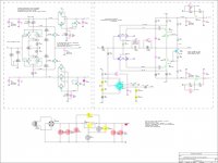
OK, starting with the snippy comment by Mark J, what can we do to IMPROVE the transformer and diode bridge in this schematic? Design first made 35 years ago. (Note, there is a (-) supply too.)
To move things along, we should AVOID a toroid power transformer, and instead use an E-I low leakage type, or an R-core to reduce RFI input from the power line. Also we should increase its rating. We upgraded to 30W per channel in the Vendetta as years passed. (30 years ago)
Also, we should use high speed soft-recovery diodes, either as a bridge, or as individual components put together to make a bridge. (D upgrade for Vendetta, from middle 1990's or 25 years ago.)
OK what other suggestions do you have? Mark? Want to go next? '-)
Last edited:
We can let the WORLD judge.
OK, starting with the snippy comment by Mark J, what can we do to IMPROVE the transformer and diode bridge in this schematic? Design first made 35 years ago. (Note, there is a (-) supply too.)
To move things along, we should AVOID a toroid power transformer, and instead use an E-I low leakage type, or an R-core to reduce RFI input from the power line. Also we should increase its rating. We upgraded to 30W per channel in the Vendetta as years passed. (30 years ago)
Also, we should use high speed soft-recovery diodes, either as a bridge, or as individual components put together to make a bridge. (D upgrade for Vendetta, from middle 1990's or 25 years ago.)
OK what other suggestions do you have? Mark? Want to go next? '-)
Or, maybe you should actually use a toroid with an electrostatic shield (if you are really concerned). That will give you smaller stray field and then you can actually put appropriate RFI filtering and a regulator that isn't from the late 1970s. It is much harder to shield against the LF magnetic fields from the transformer.
That, or join the 2000s and design a good SMPS.
A SACD Player or a streamer ?OK what other suggestions do you have?
;-)
Perhaps a silly question.
How do I work out the gain of the circuit on the left ?
Thx,
Patrick
How do I work out the gain of the circuit on the left ?
Thx,
Patrick
RFI filtering, what would you suggest?
Depends what your problem is and where in the circuit, but there are lots of options now. Common-mode chokes, ferrites, 3-terminal capacitors, X2Y capacitors.
https://www.murata.com/~/media/webr...atalog/products/emc/emifil/c31e.ashx?la=en-us
I chose a common-mode choke for the CTC-Vendetta supply in 1998. (20 years ago)
Yes, those are nothing new. Same for ferrites, etc. There are a lot of different core materials available now, though, depending on what frequency range you are looking at. Wurth and a few others have an amorphous nanocrystalline material that gives something like the low frequency characteristics of MnZn and the high frequency characteristics of NiZn.
WE-CMBNC Common Mode Power Line Choke Nanocrystalline | Passive Components | Wurth Electronics Standard Parts
The circuit on the left is a transconductance amp not an OP amp, and its gain changes with frequency. It is less at hi frequencies 2KHz and above, flat to 1KHz or so.
Like this ?...Start with the transformer and the diode bridge.

RingNot: power supply for chip amps.
Dan.
> The circuit on the left is a transconductance amp
That was what I thought.
So the right hand side is transimpedance ?
Patrick
That was what I thought.
So the right hand side is transimpedance ?
Patrick
I'm not Mark 😉 But,We can let the WORLD judge.
OK, starting with the snippy comment by Mark J, what can we do to IMPROVE the transformer and diode bridge in this schematic? Design first made 35 years ago. (Note, there is a (-) supply too.)
To move things along, we should AVOID a toroid power transformer, and instead use an E-I low leakage type, or an R-core to reduce RFI input from the power line. Also we should increase its rating. We upgraded to 30W per channel in the Vendetta as years passed. (30 years ago)
Also, we should use high speed soft-recovery diodes, either as a bridge, or as individual components put together to make a bridge. (D upgrade for Vendetta, from middle 1990's or 25 years ago.)
OK what other suggestions do you have? Mark? Want to go next? '-)
Vastly current overrate the soft recovery diodes. I like HEXFRED 25A or 30A devices. Ditch the LM317. Use a discrete reg made with a single series bipolar pass transistor also vastly current overrated. Tie the biggest capacity teflon cap you can stand from rail to rail at the power entry point of the front end.
That's where I would start. All the while being very careful not to blow the hard to get Toshiba transistors.
How and who to judge?
We can let the WORLD judge.
Yes, a WORLD of Stereophile chimp reviewers, and don’t forget the sales figures.
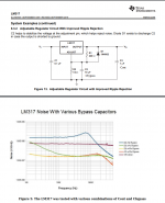
Re “humble” LM317
You might try the 10uF cap btn the adj pin and ground (and check Cout capacitance effect on noise with your load)
https://www.edn.com/electronics-blo.../Simple-circuits-reduce-regulator-noise-floor
George
You might try the 10uF cap btn the adj pin and ground (and check Cout capacitance effect on noise with your load)
https://www.edn.com/electronics-blo.../Simple-circuits-reduce-regulator-noise-floor
George
Attachments
Yes, I like to keep the 'chimps' happy, but it is really out of my hands and mostly theirs. Just like a specific talent, like dance, singing, playing a musical instrument, etc., my designs have to be put to the test with the public (all over the world) and THEY CHOOSE.
Sales, I barely made a living. Cleared $30,000 in my best year, working full time. Not really practical for a family man.
However, when a design, like some of mine, get world recognition, it shows that all the added effort to make the best possible, is not lost of deaf ears.
Sales, I barely made a living. Cleared $30,000 in my best year, working full time. Not really practical for a family man.
However, when a design, like some of mine, get world recognition, it shows that all the added effort to make the best possible, is not lost of deaf ears.
Last edited:
- Status
- Not open for further replies.
- Home
- Member Areas
- The Lounge
- John Curl's Blowtorch preamplifier part III