No.Link please
As often happens, this little item is one of those things in the indefinite middle, the grey area. I care enough about it to mention it here, but I don't care enough about it to actually make any effort searching for it. Once upon a time, long ago, when I read AoE 3rd edition the first time, I did care enough, and I did go hunting for info on Zetex's website, and I found it. I read it and reacted: wow, polysilicon base! That's pretty cool. But I didn't make a copy or save a link. And I don't care enough today, to go look again. Quoting the previous post,
They (Zetex) have a writeup on their website, which dedicated and curious people can discover, talking about this design and showing a nice 3D drawing.
If that's you, great. If not, no harm done and no money spent.
Polysilicon base doesn't make any sense from a bipolar device physics perspective. Polysilicon base contacts do, and they are a known, patented, method to lower the extrinsic base resistance.
Lacking any direct reference (Diodes Incorporated that acquired Zetex returns no results by searching for keyword "polysilicon", one patent assigned to Zetex shows the polysilicon contacts, not polysilicon base) I believe you may got fooled by a marketing ploy.
(AOE3 example) Yes, and it works as published.
if you really want beta: 820-2700 2SD2704D by ROHM Vebo > 25V. Weird. But the right thing for C-multipliers.
sot-23, 16 cent @100 < 2SD2704KT146 Rohm Semiconductor | Diskrete Halbleiterprodukte | DigiKey >
if you really want beta: 820-2700 2SD2704D by ROHM Vebo > 25V. Weird. But the right thing for C-multipliers.
sot-23, 16 cent @100 < 2SD2704KT146 Rohm Semiconductor | Diskrete Halbleiterprodukte | DigiKey >
Code:
* Rohm 2SD2704K  SOT23  hfe = 820... 2700 at 2V/4 mA
* BE-Voltage 25Vmin  0.7 Ohm Ron   20V 300 mA  200 mW
*
* Q2SD2704K NPN model
* Date: 2006/11/27
.MODEL Q2SD2704K NPN
+ IS=250.00E-15
+ BF=2.3219E3
+ VAF=100
+ IKF=25.778E-3
+ ISE=270.34E-15
+ NE=1.8069
+ BR=45.088
+ VAR=100
+ IKR=9.4796
+ ISC=411.09E-15
+ NC=2.0254
+ NK=.54182
+ RE=.4
+ RB=3.1823
+ RC=58.585E-3
+ CJE=8.7706E-12
+ MJE=.66324
+ CJC=15.709E-12
+ MJC=.53302
+ TF=3.8352E-9
+ XTF=32.147
+ VTF=472.13
+ ITF=85.294
+ TR=7.0574E-9
+ XTB=1.5000
Last edited:
During my last visit to Santa Clara in January, I noted the Rohm headquarter on San Thomas Expwy is now gone... not a good sign.
Who says this 2SD2704 is anywhere low noise? Low "on" resistance (whatever that is defined as) means low saturation, not low Rbb. I don't give a FF on non-validated Spice model.
Who says this 2SD2704 is anywhere low noise? Low "on" resistance (whatever that is defined as) means low saturation, not low Rbb. I don't give a FF on non-validated Spice model.
Last edited:
Polysilicon base doesn't make any sense from a bipolar device physics perspective.
I have probably the only remaining samples of some NPN's made by Philips in the 80's no poly but the lowest rbb I have ever seen reported. From the days when you could woo engineers by mentioning audio, these were made for the most extreme MC's of the day. No real product ever came out of this, I ended up with some samples as a professional courtesy from the authors.
Interesting, did these Philips devices ever got a tentative code name? I know somebody that worked at Philips in the time, would love to get some details if possible.
LT1115 comes close. (Bonsai mentioned this 8 legs and I had a look).Once you get below 0.5nV/rtHz I no longer see a need at least until I get a nagatron ribbon cartridge.
Three circuits for cartridge signal amplification
https://www.analog.com/media/en/technical-documentation/data-sheets/lt1115fa.pdf
George
LT1115 is a dinosaur from the Cretaceous era of linear IC technology. Check out the ADA4898, or the LMH6629 if low voltage rails fancy you.
Thanks.
Imagine I consider it one generation younger that the ICs I have in my bins.
I surely live in Jurassic period (so is the vinyl playback) 😀
George
Imagine I consider it one generation younger that the ICs I have in my bins.
I surely live in Jurassic period (so is the vinyl playback) 😀
George
"So zero analysis of the actual problem or solution? Shame on you. Have my cobblers awl (northampton boy). "
I told you what the problem is: bass speakers flapping around - due to record warp/off centre - at subsonic frequencies. If this is not caused by high amplitude subsonic frequencies and there is a cheaper alternative than a 1% resistor please tell me. Seriously.
I told you what the problem is: bass speakers flapping around - due to record warp/off centre - at subsonic frequencies. If this is not caused by high amplitude subsonic frequencies and there is a cheaper alternative than a 1% resistor please tell me. Seriously.
I expect better from you (please take that in the right spirit I consider you a respected friend). The circuit I am talking about operates always in small signal mode and has no slew rate, it is -90dB or so THD at line level and does not get to 1% distortion until several 100's of mV at the input. All performance aspects are far beyond the capabilities of an LP and stylus.
You're taking me too seriously on this issue.
I'm just challenging you on your statement 'why bother - its an LP' when you can get 10x better performance with a jelly bean 5534.
I am certainly not detracting from your work or your phono amp design
🙂
LT1115 is a dinosaur from the Cretaceous era of linear IC technology. Check out the ADA4898, or the LMH6629 if low voltage rails fancy you.
I mentioned the LT1115 simply because it was the first example I saw that showed a phono amp that used the single resistor trick to attenuate subsonic frequencies.
I don't use and never have used the LT1115. For standard MM work, I think the 5534 or some of the newer low noise opamps do just fine while JFETs work surprisingly well for MC (BF862 - I have a stash)
Scott, I worked at Philips (then NXP) for ~20 years. If your devices were experimental they were probably made in Hamburg (all small signal bipolar stuff is still fab'd there) and everything is assembled in China or Thailand (Hong Kong was closed about 10 or 12 yrs ago). Before I retired, they were churning out >70 billion small signal devices a year (about 25% market share).
Only other place they may have been fab'd at was Hazelgrove near Manchester, but then it would have been power devices (TO126 and up) - but that bipolar activity was moved to China in 2002 and the focus became triacs and thyristers (huge Asian home appliance market) and high volume CFL lighting transistors - all gone now to LED.
Measurements please.
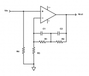
Ideal RIAA stage: T(s) = Adc x (1 + s x 318uS) / ((1 + s x 3180uS) x (1 + s x 75uS))
If s -> infinity, T(s) -> Adc x 318uS / (s x 3180uS x 75uS) = Adc / (s x 750uS)
Now here is the active RIAA stage. At very hf, the two eq capacitors are a very low impedance, so replace them each with a short.
The T(s) = 1 + (zfeedbacknetwork)/R3. If the (zfeedbacknetwork) -> 0, then T(s) -> 1, and you have unity gain at hf.
No matter how or what you measure, T(s) = 1 is not the same as T(s) = Adc / (s x 750uS). This problem is well known.
Attachments
I don’t doubt there is a zero at HF. As long as conformance is good to say 50 kHz and thereafter it rolls off ultimately reaching 20 dB/ decade, I don’t see the problem.
However, more to the point, I’ve built and measured these things and the conformance using an inverse RIAA is exemplary. Square wave testing would quickly show up anything out to say 1MHz.
BTW Lipshitz’s paper talks about a passive LPF after the main active stage to bring the RIAA conformance into line at HF (so c. 10-20 kHz). The filter -3 dB point is usually set to 50 to 100 kHz. I use a spread sheet then LTspice to optimize it and then measure it to confirm the conformance.
I’ve built and measured these things and the conformance using an inverse RIAA
is exemplary. Square wave testing would quickly show up anything out to say 1MHz.
Yes, perhaps the hf shelf limitation of the inverse RIAA box is approximately correcting the hf shelf of the non-inverting RIAA stage. Two wrongs making an apparent "right".
Last edited:
"So zero analysis of the actual problem or solution? Shame on you. Have my cobblers awl (northampton boy). "
I told you what the problem is: bass speakers flapping around - due to record warp/off centre - at subsonic frequencies. If this is not caused by high amplitude subsonic frequencies and there is a cheaper alternative than a 1% resistor please tell me. Seriously.
So you wanted a speaker deflappy function. Fine. We have different goals in vinyl optimisation. My fool's errand is more foolish that yours 🙂.
Btw greetings from Sedgeford. Visiting for the weekend.
Gee, that Black hole picture, sure looks a lot like what we figured it would look like. Still, I am impressed that they got it anyway. I would have been an astronomer if I had not be dissuaded in high school that it there was no employment in the field, so I drifted for awhile, until I found electronics.
My genius young woman sent me this..... Sara is so happy it was another young woman who did it;

Katie Bouman is only 29 and she started working on this subject since she was a teenager.
-RNM
Last edited:
@Syn08 agree with you. I'm just regressing to the 70s and messing with classic balanced mic preamp topologies for this iteration of MC preamp. After that who knows which way I will go 🙂.
Even if an op amp with bipolar 15V supplies is used for the first stage, the overload point is not an issue. Say the first op amp can output 13V peak on a 15V supply. From past research by Shure etc. a mm cartridge will output less than 100mV peak on a hot record. Then the maximum gain for the first linear stage before clipping is 13V/0.1V = 130 times or 2dB.
We only need 60dB for both stages combined to get 40dB midband RIAA gain, since there is a
Of course. My reference was assumed to be a single opamp RIAA circuit.
In my passive EQ'ed RIAA, I also used two stages.... discrete and 24v bipolar supplies. I didnt use Any EQ around either stage. All passive EQ between stages. Very accurate sound that way. Still very quiet, too.
THx-RNMarsh
Last edited:
Just curious, very accurate to what?Very accurate sound that way.
If you've decided no progress is possible then there isn't much else for me to say, and, perhaps, more to the point, no question for you to answer.
We're done. I'm not really sure what you've been getting at with your posts. I've made it pretty clear that I'm quite pleased with the results I get using the method of positioning the speakers that I use. No sure why you think you have something to add to that as you are unfamiliar with the procedure and the results. If you do have any genuine interest in the procedure, then perhaps you could just try it for yourself. The simple necessary steps have been well presented. It is easiest to do with the designated recording of Ballad of a Runaway Horse, though that is not exclusive. It is just moving the speakers around in the prescribed manner to find the best and smoothest bass and then finding the best and most solid centered image of the voice. And in the end if you do not like the result, you just return the speakers to their former position. Beyond that, there is no more discussion.
- Status
- Not open for further replies.
- Home
- Member Areas
- The Lounge
- John Curl's Blowtorch preamplifier part III