Its too late tonight. I'll outline two commercially viable solutions to the driver position sensor I have used, tomorrow. I have not made subwoofers commercially for many years so no reason not to share. They can be as cheap as $1 to implement with some smarts and quantity, especially today. However $1 is considered a lot to add to a BOM for high volume boxes that are called "speakers" in the mass market.
And on a quite different track I need to build a sensor to tell when the 55 gallon drum on my dust collector is full. <snip>
Dust collectord should always be outside unless they have HEPA filter bags. I can't count the amount of shops that will have long term people develop problems from breathing wood all day... it is just silly. And it is way worse if you cut stuff like cedar and others.
Also the ducting should be solid entirely, with only the utmost ends being flexible... unlike the typical 10-15ft of flex I have seen.
Personally I wear an organic vapor/hepa mask when ever I am having to be in anywhere inside around saw dust.
The idea of weight might work on your bags. But what about a small window so you can just see it? The last time I worked in a place no one really gave a hoot what we did, but we never had to build outside of the shop. Where you are sounds strict!
Dust collectord should always be outside unless they have HEPA filter bags.
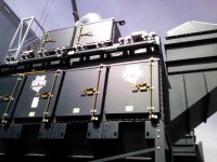
😀 I am the right person here. A photo attached is from installation 6 years ago. But, I do not feel like chatting about 😉
Attachments
What we ask a speaker to do is against all known laws of nature 🙂 Ideally to follow the signal perfectly it needs to have no resonances and instant reaction. Some of the motional feedback techniques will have their own imperfections and likely be only slightly better then the speaker they're trying to control.
We need some form of motor, is there such a thing as a linear stepper motor? Could a diaphragm be moved by laser?
We need some form of motor, is there such a thing as a linear stepper motor? Could a diaphragm be moved by laser?
Why not sense capacitance from coil former to the magnet assembly?
In the Backes & Müller BM40 they sensed the capacitance between the membrane and a mesh in front of it. Was patented and the cost was astronomical, already 30 years ago. The patent should have timed out by now.
Philips had a piezo sensor to measure acceleration. Takes some integrators.
A true bifilar coil is a nice solution. The trick is that both coils are driven and working as the sensor at the same time. To get motion control, we must extract velocity, the microphonic voltage, by subtracting the Ze*i(t) voltage from the terminal voltage. This is done with a bridge in the usual way. Once the bridge is balanced against the static VC impedance, the problem is the dynamic unbalancing of the bridge via thermal VC resistance changes. David Birt (see eg here) has developped a servo that keeps the bridge in balance and this servo can greatly improved with dual coils. Both carry the same AC current but a small opposing DC test current, by adding up the latter we have a sensor signal for instantaneous VC temp that is almost completely free of AC, which makes filtering of it much easier than with a single coil. Also, the test current doesn't offset the coil and can be made as large as required.How well has the dual voice coil worked -- using one coil for correction/feedback/pickup? Some shaping may be needed but not too complicated IMO.
Of course the reactive part of the static VC impedance needs to be really constant and stable for an extractor bridge to work properly. Generously underhung VCs can afford that, or really clever overhung design. Also, making the pole piece and top plate non-conductive or at least sliced so that eddy currents are non-existent/low. DIYA member @soundbloke has several posts on this (and current drive, and the Birt bridge).
Like with many other sensors, the biggest problem is handling overdrive, in this case it's a severe problem because the sensor has the same linearity range as the actor. To overcome this, one could design a bifilar coil with two taps, only the underhung center section would be used as actor while the outer sections would be part of the sensor.
This tapped scheme also works without control loop where the inner underhung section receives a full range drive signal whereas the outer sections are used only for mid/high frequencies and would be constant BL throughout the whole mechanically possible range of motion so even when excursion maxes out from strong LF signals the higher frequencies are still reproduced faithfully (assuming we're in the dominantly mass loaded range of frequencies). All three sections are terminated with the same impedance to provide proper linear damping even way beyond Xmax which is a key point in getting clean overdrive behaviour and recovery.
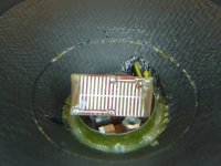
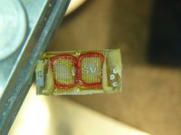
Below some photos of the velocity sensors in the Backes & Müller woofers.
As mentioned before, they are orthognal to the drive coil and use an extra small magnet system, humbucking and shielded (at least a bit).
Attachments
If the midrange is driving an overhung section of coil, it will cause modulation of the signals because the Bl is dropping out of the gap.
Anyone performed two tone testing to look for it?
As for my previous mention of dipole coil, I explain more..
A simple flat coil placed against the vc solenoidal coil will not pick up the vc current field for the most part. It will only be sensitive to movement in the gap flux.
Using two, wired opposing series but one at front edge, one at back edge, will provide only a BL difference signal that provides positional information. The vc current field will cancel in the opposing coil voltage. This signal can be used with the drive signal history to provide a compensation for BL nonlinearities. These coils could be simple pc traces on a two layer kapton sheet, and glued to the former or over the coil OD. Yes, there will be a thermal transfer hit.
Jn
Last edited:
Thanks !Below some photos of the velocity sensors in the Backes & Müller woofers.
As mentioned before, they are orthognal to the drive coil and use an extra small magnet system, humbucking and shielded (at least a bit).
SENSOR FOR DETECTING A MOVEMENT OF A LOUDSPEAKER MEMBRANE
George
We could use too those little acceleration captors used in smartphones. They are so light. But as double coils, it is difficult (impossible ?) to integrate the acceleration in order to get a precise and reproducible position value.
Using a laser to measure the position should be better, but what about the price of such a study and system ?
I don't know if it is worth the pain for the benefit.
As many, I played with double coils servoed speakers in the early 70's. With results, how to say, mixed ?
As most of the companies, like Philips, 3A etc. the problems are so complex that they all ended up giving up the idea.
That's really close to how the insides of a cutterhead is made. There is a good chance it has been proposed in the lit in the past. it would be a difficult patent to defend.
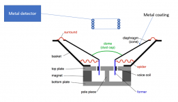
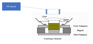
Here are the two systems we used in the Entec subwoofers.
The first gen used a metal detector circuit to get the position of the cone. We glued foil to the driver and returned the DC output from the metal detector to a summing junction. We had a DC trim to center the system. Problems: the DC was not really stable and it could pick up the output of a CRT TV at 6 feet and give a beat tone with the metal detector.
Gen 2 addressed these issues and is more linear. We drive the coil in front of the driver with an ultrasonic signal. It would be picked up by the voice coil projecting past the pole piece. The magnetic structure effectively shielding the rest of the coil from the signal. We then used a bandpass filter and a synchronous detector to recover the DC proportional to the projecting voice coil. I added a circuit to delay closing this loop until the DC had settled.
If you do this you then need to shape the response of the system. The cone will move directly proportional to the voltage which translates to a rising response with frequency. You need a high pass filter because it can respond to DC. You need to manage what the system does when it clips. The servo will go nuts since it will want the amp to drive harder into clipping.
We also had a motional feedback loop extracting the back EMF from the driver using a bridge network.
The electronics to implement this was pretty involved. Could be smaller and simpler today.
The ideal solution would be an LVDT structure built into the magnetic structure of a driver Measuring Position and Displacement with LVDTs - National Instruments I used an LVDT chip in the second gen Entec design because it had a lot of the key building blocks in it.
Still whether you are sensing the voice coil or the diaphragm you have a max frequency you can close this loop around. The limits come from the speed of sound in the materials. Bigger drivers will have a lower HF limit since it takes longer for the sound to propagate through them. Using an acoustic sensor also has this finite limit, working fundamentally the same as a noise cancelling headphone.
Attachments
Using an acoustic sensor also has this finite limit, working fundamentally the same as a noise cancelling headphone.
I was thinking more of an absolute barometric pressure transducer in a closed box to tune the system. I'm not a speaker guy maybe this does nothing for you.
Its a great idea but its limited by the speed of sound. In a sealed box it may work pretty well. You would need to translate its output to the desired acoustic response and deal with the stability issues around the box resonances. All possible but not simple.
What do you need?It is a nice design, but limited use for my application
#1. Simple but effective --- what are major issues, if any, with this approach? Or, minor issues.

#2. I would imagine the simple THD reduction scheme I demonstrated in PA/Spkr would be useful concept if applied to a phono cartridge as well.
I don't think that has been done before.
?
THx-RNMarsh
#2. I would imagine the simple THD reduction scheme I demonstrated in PA/Spkr would be useful concept if applied to a phono cartridge as well.
I don't think that has been done before.
?
THx-RNMarsh
Last edited:
#2. I would imagine the simple THD reduction scheme I demonstrated in PA/Spkr would be useful applied to a phono cartridge as well.
I don't think that has been done before.
Unlikely, the tracing distortion probably dominates in almost all cases.
doesnt matter. Work one down and then go after another.
The problem is similar as coil/magnet distortion generated with a speaker. IMO the cartridge is a lot worse than speaker...
-RM
The problem is similar as coil/magnet distortion generated with a speaker. IMO the cartridge is a lot worse than speaker...
-RM
Last edited:
doesnt matter. Work one down and then go after another.
The problem is similar as coil/magnet distortion generated with a speaker. IMO the cartridge is a lot worse than speaker...
The reciprocity of a typical motor in a cart does not support most/any of the post-facto feedback techniques. Building a cart ground up for it or some guessing feed forward technique, maybe. Very linear zero reciprocity techniques like strain gauge and optical (not the laser TT) do not IME show dramatically reduced transducer distortion only the benefits of $$$ stylii and fussy alignment. Wagging the dogs tail is a myth in this case IMNSHO.
Take a test LP you can see by eye the displacement for a 500Hz tone that puts out 5mV, apply 5mV to the cart the stylus does not move.
Last edited:
- Status
- Not open for further replies.
- Home
- Member Areas
- The Lounge
- John Curl's Blowtorch preamplifier part III