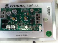
Well I have been busy modifying 150 microphones to change from external power supply to accepting phantom power. The manufacturer not only no longer offers the option, but has no one left to do it and does not even show a correct schematic.
So I splurged on a hot air rework tool and spent a bit of time removing 300 resistors and then adding 150 more. Each unit was tested after modification. Found one bad one. It was a cold solder joint on the output connector. As these microphones go into a very high security facility seemed worthwhile to check everything out.
So been delayed in more capacitor play. First a couple of issues. Distortion does drop V^2 or V^3 as Scott mentioned and ruining one of my quiz questions for Derfy. Not surprisingly when the voltage across the capacitor drops so does the distortion contribution. Also I was able to verify that reverse bias on polarized capacitors does increase the noise floor.
In today's example not that the AP shows a bit of it's dynamic range limit of around 110 dB.
Attachments
Richard, for all your worry about DA, can you show an ecample of swapping otherwise well matched caps in bypass application and seeing material differences?
Bypass? I dont think DA matters there, that I can think of. So nothing but Z plots of parallel caps to show. But, I would take the opportunity to tell audio makers to stop placing PS bypass at the rectifier/filter caps. Put bypass close to the circuit.
The film caps for bypass have lower Z at higher freqs than large value electrolytics. Again a matter of ratio ... if circuit Z values are low (like maybe low noise ckt) then larger C bypass is needed. One size does not fit all. Basic info but I see a lot of DIY and mfr also placing bypass far from circuitry.
THx-RNMarsh
Last edited:
Otherwise it's a lot of words to hand wring, especially in light of so many tests showing extremely low distortion amplifiers with ac coupling.
The DA at least with respect to the mechanism that gives the recovery after shorting is a DC phenomena unless there is a change in DC level this aspect does not factor in. The DC is applied at turn on and settles soon after, for an AC coupled circuit there is no further application of DC. As for distortion no purely additive process without a non-linearity can create new frequencies. Capacitors can have distortion making mechanisms, that's accepted, but they are low order and generally follow a simple polynomial expansion. That is like (some of) Nelson's and JC's amplifiers the distortion goes to 0 as the level goes to 0 by a power law series.
Abrupt discontinuities at 0 are non-physical. As I said before radio astronomers would die for a rectification mechanism that operated at the mV level.
Last edited:
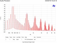
So been delayed in more capacitor play. First a couple of issues. Distortion does drop V^2 or V^3 as Scott mentioned and ruining one of my quiz questions for Derfy. Not surprisingly when the voltage across the capacitor drops so does the distortion contribution. Also I was able to verify that reverse bias on polarized capacitors does increase the noise floor.
In today's example not that the AP shows a bit of it's dynamic range limit of around 110 dB.
Nice. caps? size, value, type and load Z etc?
-RM
comment on DA being a DC phenom.... if signal had DC component or average of DC equiv, DA can be considered potential suspect. But depends on circuit Z to Rda ratio. As a PS electro bypass that ratio is very high and so not an issue there.
Last edited:
I believe everything had been told about this capacitance subject since decades. If I remember well, the Jung and Marsh paper was published in 1980.
And is available for free.
No offense to honest efforts, but compared to the AES paper I posted about and Bateman''s work, the Jung and Marsh paper is not the best reference.
Jan
Also I was able to verify that reverse bias on polarized capacitors does increase the noise floor.
Ed another point without bleeders the series connected caps have an undefined DC voltage. Usually everything ends up at O but you never know.
Ed another point without bleeders the series connected caps have an undefined DC voltage. Usually everything ends up at O but you never know.
In fact you never know. So avoid series connected caps, if there is no voltage distribution definition by even high resistance divider circuit.
Ed another point without bleeders the series connected caps have an undefined DC voltage. Usually everything ends up at O but you never know.
Actually I did check with a meter. Absolutely not uniform. For forward bias I wanted to be sure each capacitor had DC on it greater than the AC peak to peak.
For reverse bias I didn't really worry the effect was so large!
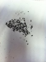
My next venture will be into some film capacitors.
RNM, all capacitors 1 uF the ones just shown are 35 Volt DC rated. Hold your mouse over the thumbnail to read the part number.
Actually I did check with a meter. Absolutely not uniform.
Unless you use an electrometer you have the classic problem of the measurement disturbing the system.
Bypass? I dont think DA matters there, that I can think of. So nothing but Z plots of parallel caps to show. But, I would take the opportunity to tell audio makers to stop placing PS bypass at the rectifier/filter caps. Put bypass close to the circuit.
The film caps for bypass have lower Z at higher freqs than large value electrolytics. Again a matter of ratio ... if circuit Z values are low (like maybe low noise ckt) then larger C bypass is needed. One size does not fit all. Basic info but I see a lot of DIY and mfr also placing bypass far from circuitry.
THx-RNMarsh
Color me confused about the worries of DA again, then? I thought the concern was at the input. Agree entirely that it's a waste to put bypass at the PSU rather than immediately at the load, but a quick look at the series inductance will tell you that. There's a reason it's called "local" 🙂
But, for anything passing a healthy current and in audio bandwidth, it's hard to beat something like a 10 uF x7r sitting right on the pins of your output transistors. The lead inductance on your larger output transistors generally obviates any advantage from a wider bandwidth, smaller capacitance part. Haven't looked more carefully if one does SMD driver transistors.
Scott -- Thanks for the info, and yes, outside of power up/power down transients, I don't see it playing a big role. I'm really trying to figure out why the worry on behalf of Richard/John/et al, and in which specific parts within a circuit. I figured the concern was in AC coupling the front end (if there is any ambiguity)
It appears they did everything they could to make things worse. In reality there would be 20V or so DC bias and 100mV signal would be a fairly high SPL.
Would you measure one of JC's or Nelson's open loop amps at just below clipping and compare it to a high feedback design that has no distortion until it clips?
Yes. In stereo behavior has a variety of factors. This is similar to expecting a speaker driver to show all of its colors in a hearing test, when you're using a digital crossover in an infinite baffle.
Unless you use an electrometer you have the classic problem of the measurement disturbing the system.
Electrometers are for wusses, better use a $5 multimeter, then claim a quantum effect and invoke Heisenberg.
I figured the concern was in AC coupling the front end (if there is any ambiguity)
There are some valid concerns in speaker crossovers, but Dick Sequerra himself told me there was nothing to gain in upgrading the caps in his speakers. Talk about the horses mouth.
Electrometers are for wusses, better use a $5 multimeter, then claim a quantum effect and invoke Heisenberg.
Actually electrolytic capacitors have a yet to be discovered process where they can destroy charge. It must go directly to dark energy.
I coined the phrase 'no capacitor is the best capacitor' to side step which cap dielectric is better and under what conditions and DBLT et al on coupling caps.
THx-RNMarsh
I'm not sold on that. I think it depends on the equipment. For example if you have transformers maybe that can hold true.
But in general, even while capacitors impart some character, the benefits to the complex impedance of having a capacitor that doesn't fall on its face under DC bias probably shouldn't be underestimated. This is especially a concern when mixing manufacturers.
I had a weird experience with an amp one time. At the time I was playing with some lytics that were cheap and known to sound decent. Then to compare I bypassed them with a film cap. The amp sounded way better. Here's where it gets interesting, on a second look I realized I hadn't bypassed the lytics, and actually accidentally simply added the film cap in series with them. What I did was I stopped the lytics from being biased into oblivion (with no more than 12v).
To antagonize this observation some more, I'd go as far as to say a notable amount of capless amplifiers end up having a similar unforgiving fatigue sound to them.
Every parasitic has its affects... depends on circuit and Z of circuit as to which and when.
If you were talking about circuits with input Z of > 1meg or a SS with input Z of 1K. Makes a difference.
as I pointed out many times..... electrolytic leakage might or might not be a problem in your design. C change with frequency may also be an issue for you. All by themselves, they have no affect on thd. As would not high esr or esl.... no affect on thd.
end results all depends on your circuit parameters and what you need.
In high current apps (like speaker xover) the met film will have its esr modulated and increased esr (heating). You should then use film and foil if high current is to pass thru cap.
At the time of WJ and RM cap article there were a lot of tube products still in use and in the SS designs which mimicked their topology, poor quality electrolytics were used. Today, the electro is a lot better (lower thd). but they deteriorate all over the place. C changes might be important in a specific place. Like greater and greater LF roll off over time.
For the record, I did a lot of thd tests of caps also... Just didnt write anything about them. espec of back to back polar and paralllel polar and biased polar. Its just easier to go to film cap.
i had other reason for MY app to get ride of as many caps as possible on the system's accumulated LF end... (HPF ).each product rolling off, added up in a system and group delay was also an issue to me. But I never mentioned that about caps, per se.
THx-RNMarsh
![Capacitance_versus_frequency_.tif[1].jpg](https://www.diyaudio.com/community/data/attachments/607/607999-e2051b78268023407deeefb05c67f630.jpg?hash=4gUbeCaAI0 "Capacitance_versus_frequency_.tif[1].jpg")
![img_electronics_primer_vol7_1[1].gif](https://www.diyaudio.com/community/data/attachments/608/608001-19fced418cb0786db252ae977649db12.jpg?hash=GfztQYyweG "img_electronics_primer_vol7_1[1].gif")
(30-50% change may Not be your idea of good service life)
If you were talking about circuits with input Z of > 1meg or a SS with input Z of 1K. Makes a difference.
as I pointed out many times..... electrolytic leakage might or might not be a problem in your design. C change with frequency may also be an issue for you. All by themselves, they have no affect on thd. As would not high esr or esl.... no affect on thd.
end results all depends on your circuit parameters and what you need.
In high current apps (like speaker xover) the met film will have its esr modulated and increased esr (heating). You should then use film and foil if high current is to pass thru cap.
At the time of WJ and RM cap article there were a lot of tube products still in use and in the SS designs which mimicked their topology, poor quality electrolytics were used. Today, the electro is a lot better (lower thd). but they deteriorate all over the place. C changes might be important in a specific place. Like greater and greater LF roll off over time.
For the record, I did a lot of thd tests of caps also... Just didnt write anything about them. espec of back to back polar and paralllel polar and biased polar. Its just easier to go to film cap.
i had other reason for MY app to get ride of as many caps as possible on the system's accumulated LF end... (HPF ).each product rolling off, added up in a system and group delay was also an issue to me. But I never mentioned that about caps, per se.
THx-RNMarsh
(30-50% change may Not be your idea of good service life)
Last edited:
You misunderstood. I was not considering anything, just noting an observation. That makes the rest of your post irrelevant, which I therefor not quoted.
And no need to thank me for downloading a $ 33 paper, reading it, making shots of relevant parts and posting those. Because I know there are others that actually look at the contents rather than get all excited by the name of the mailman.
Jan
Thanks Jan.
i had other reason for MY app to get ride of as many caps as possible on the system's accumulated LF end... (HPF ).each product rolling off, added up in a system and group delay was also an issue to me.
Which your current set up is certainly a success in. You can run digital into the power amps and everything is then under tight control. Advances in DSP have allowed for all these worries from the last century to be just wiped out. Gotta love technology 🙂
Which your current set up is certainly a success in. You can run digital into the power amps and everything is then under tight control. Advances in DSP have allowed for all these worries from the last century to be just wiped out. Gotta love technology 🙂
yes. It was a 'quantum' leap to go direct-coupled at that time. And, with DSP for cross-overs etc, we just keep moving right along.

-RM
Unless you use an electrometer you have the classic problem of the measurement disturbing the system.
Yes the measurement will read low due to the meter's load. As the test was to be sure the voltage was above a minimum that was not a problem.
- Status
- Not open for further replies.
- Home
- Member Areas
- The Lounge
- John Curl's Blowtorch preamplifier part III