someone should have said it for you.BTW sorry to say Joe in some circles we are the experts.
Joe, since you seem to put your trust in the references, do you think that Analog Device would entrust the design of its integrated circuits to amateurs ?
What point, EMF and impedance are the same? You are clearly not communicating with your experts. You left jn out, BTW sorry to say Joe in some circles we are the experts.
Joe is not far from Mr. Bybee mentioning his mentee Feynman in support of his quantum devices, so why bother? It is unlikely either will move one inch from their trenches.
Last edited:
someone should have said it for you.
Joe, since you seem to put your trust in the references, do you think that Analog Device would entrust the design of its integrated circuits to amateurs ?
I'm not even remotely an expert on speakers but it's the basic stuff that bothers me, jn is an expert on the magnetics. Joe has resources here and he just ignores/insults them. I've said several times Joe's speaker might have some merits to some people, why cloud everything in this fog of sloppy thinking?
Does JR mean to indicate that the level of back EMF follows a curve like the speaker Z?
?
-RNM
?
-RNM
why cloud everything in this fog of sloppy thinking?
The Marketing Law of Perception
Marketing is not a battle of products, but rather a battle of perception. Successful brands sell benefits, experiences, ideas, messages – not features and facts. The perception of an offering is more influential than the actual facts.
No, I do not think he is deaf. It seems he merely prefers an effect chain with gross distortion of the drivers, cartridges and others kept as pristine as possible, and/or lazy to measure the acoustic output. 🙂No comment, my deaf friend. You are free to listen with your eyes, looking at response curves and distortion numbers. ...
Sure. The first part was simplistic but correct. You used the proper terminology, and you did not make any amazingly inaccurate statements. The fact that you were able to accurately discuss dissipative loss as consistent with measured spl is good, that is a start. You even accurately stated that it was close but not exact, as the bulk of energy loss in a speaker running maybe half percent efficiency is indeed dissipative. For good horns, the acoustic conversion throws those numbers off.It was a typo. No jumping. Moderator has corrected it, I thank him.
You said "You were OK here, but..."
Could you please explain that.
You and your expert will not yet understand eddy dragging, eddy dissipation, or any mechanical dissipation nor how to measure them, nor conversion efficiency vs coil position, box compliance multi order storage/dissipation, or even the simple concepts like inductive shedding vs coil position with multiple frequencies.
Neither of you even know how to interpret an inductive frequency scan result, why typical meters measure negative inductance on one side of resonance.
Nor do you have the foggiest idea how to split out resistive coil losses from acoustic output, I suspect your expert doesn't understand why eddy dissipation shows up on an LCR meter.
As was pointed out, you do not understand the distinction between emf and impedance, you consistently botch that. The fact that your expert is supporting bad concepts tells me your expert "isn't".
You are somewhere between 25 and 35 years behind the technology I do for a living, so if you are "encouraged", it should be because I still bother to try and fix your poor understanding of fundamental concepts despite your condescending remarks. And when I say you are decades behind me, I mean the stuff you are working on is.... your statements and errors are 45 years behind, I learned what you are trying to discuss in 1974. (Now you've gone and reminded me that I'm an old fart..thanks a lot.🙁
As I offered, I would be more than happy to correct both your and your "expert" (Should he actually exist), I have been quite patient in engaging you to try to help you.
Have your "expert" pm me, I'll be happy to help him.
Jn
Just because someone is an authority on a subject does not mean they are 100% correct or infallible. It's a textbook logical fallacy. The claim should be evaluated, not the person making it.
Agreed!
I even said that myself, did you not read that?

What point, EMF and impedance are the same?
At what point did I say that they are the "same" - because I don't recall using that word in that way. If I said it, then I take it back and say sorry. I will try again, let me know exactly where I am at fault. I can take it, and I have been wrong before. That is how I learn.
Again, I will refer to a impedance measurements, of which I have made untold thousands. Anything below Re (say 6R for a typical 8 Ohm driver) is indeed resistive. The sound pressure level, measured by a real microphone, is proportional to the current. The heat generated across the Re (Vre*I) would also be approximately proportional to the heat dissipation (allow 1% error due to the driver efficiency). The part of the measured impedance above Re = 6R is the complex part of the impedance. That part of the impedance is caused by the back-EMF of the driver and above 200 Hertz is inductive back-EMF and at LF is the motional back-EMF. Interestingly I heard this described also as the motional impedance of the driver. So somebody else has said it, so I claim nothing new.
This is about as basic as it gets, what the amplifier sees beyond it own output impedance and cable resistance:
So take any frequency of an impedance plot, measure Re and subtract it from the total impedance and the measurement has revealed that part of the impedance.
The green line roughly scratched in here is representative of the DC resistance or 'Re' of the driver.
That Part A and Part B of the total impedance, that goes way back to the 1960's - the only difference is that I call it Part A and Part B for simplicity.
What point, EMF and impedance are the same? You are clearly not communicating with your experts. You left jn out, BTW sorry to say Joe in some circles we are the experts.
Experts? How about Neville Thiele and Richard Small? Scott, may I respectfully ask, do you know who they are? It all goes back to them. Right here in this town where I am right now, just down the road.
I am not the one seeking an argument, OK?
The impedance is measured from a constant current source, where the voltage becomes proportional impedance. That impedance is measured in Ohm. That technique was invented by A. Neville Thiele.
So can we see the connection between volts and impedance now? It is more correct to say that they are proportional and hence the are linked. You cannot deny that, and if you do, then may I ask that you make the case. I promise, I will listen, fair enough?
To continue, Thiele measured the impedance, and if you know the "textbook" he called it a "constant current" measurement. The voltage measured by a fixed current is proportional to the impedance.
But Thiele's equations are based on manually measuring and separating the Re part off the impedance from the the total impedance measurements. So he realised Part A and Part B as part of his equations. Again, this is undeniable.
Nothing new, no new claims. This is sixty plus years ago!
I live here in Sydney, the home of Neville Thiele and lived near Sydney University, this is where it all happened. Thiele passed away in October 2012, but I can pick up the phone right now people who knew Thiele, people who studied with Thiele. I had some dealings with Small myself, I even had some wrong notions that he needed to set me straight on. And I listened and I learnt from him.
Where is the better experts here? Please?
Hands up... please?
Last edited:
The impedance is measured from a constant current source, where the voltage becomes proportional impedance. That impedance is measured in Ohm. That technique was invented by A. Neville Thiele.
Are you serious? This is hopeless, George I'm not going to drag this on it will dissipate of its own accord.
Last edited:
I have no idea what he is trying to mean. His technical explanations remind me of Norm Crosby.Does JR mean to indicate that the level of back EMF follows a curve like the speaker Z?
?
-RNM
I've attempted to help him, so far all I get is hits upside the head.
Jn
Are you serious? This is hopeless, George I'm not going to drag this on it will dissipate of its own accord.
Yes he is serious. Theile used a time machine, travelled back in time and taught Ohm the rule of law.. Ohm, being unable to attribute the understanding to a time traveler, claimed the law as his own.
I bet Theile also taught Faraday, Maxwell, Helmholtz, Gauss, Tesla, Ampere and Edison.
Jn
Ps.. So Joe..."approved by peers of note" as you stated previously, means one who is dead, and another who you do not have contact with but he had to correct you on errors. So, by "peers of note, you mean the work of another that you are trying to understand.
Trying to understand this stuff is a good thing, I still think you can learn it.
Last edited:
I'm not even remotely an expert on speakers but it's the basic stuff that bothers me, jn is an expert on the magnetics. Joe has resources here and he just ignores/insults them. I've said several times Joe's speaker might have some merits to some people, why cloud everything in this fog of sloppy thinking?
His website shows more than speakers to sell. DAC upgrade, analog clock buffer, power supply upgrade, CD DVD or Blu-Ray player upgrade, amp, interconnect cables...etc.The Marketing Law of Perception
Marketing is not a battle of products, but rather a battle of perception. Successful brands sell benefits, experiences, ideas, messages – not features and facts. The perception of an offering is more influential than the actual facts.
Sure. The first part was simplistic but correct. You used the proper terminology, and you did not make any amazingly inaccurate statements. The fact that you were able to accurately discuss dissipative loss as consistent with measured spl is good, that is a start. You even accurately stated that it was close but not exact, as the bulk of energy loss in a speaker running maybe half percent efficiency is indeed dissipative. For good horns, the acoustic conversion throws those numbers off.
You and your expert will not yet understand eddy dragging, eddy dissipation, or any mechanical dissipation nor how to measure them, nor conversion efficiency vs coil position, box compliance multi order storage/dissipation, or even the simple concepts like inductive shedding vs coil position with multiple frequencies....
Actually, I have no argument with anything you say. As a speaker designer I deal with problems and solutions. What I have stated is not incompatible with what You have said. I recognise that may be difficult to grasp, but why does people here think that I am trying to insult them?
So I stand by what I said. Indeed, what I have said so far is only Stage One, and we are up to Stage Three now. So I won't go down that path any time soon.
One of the guys who is part of this exploration is also a person with significant expertise in your field. I would not mention his name here, but if you should PM me, I could let you know. In fact, in the future I hope he will do an AES paper on the subject, he surely would be much better suited to this that I.
I have stated this and I would like (indeed appreciate) your thought on this: Make the amplifier produce the same current at all frequencies, that is EQ the current down to the Re of the driver.
It would look like this (same as in the previous post, but here it represents to Zobels for above 200 Hertz and an LCR for the Fs peak.
An externally hosted image should be here but it was not working when we last tested it.
So there we have the two results, one equalised current and the other not.
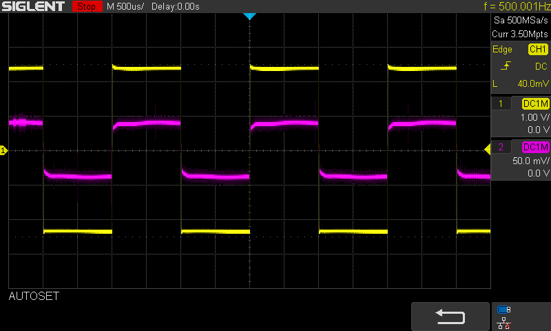
Now let us put a square wave through it when current EQ is applied and see what it does on the current side of the amplifier (note I chose my words carefully there):
An externally hosted image should be here but it was not working when we last tested it.
As you can see, this is 500Hz, but you can choose any frequency you like. Carefully adding elements to the EQ (or some would call conjugate) and you can get an even better result.
Now here is the question:
Driving that driver and varying the impedance from zero to infinity, both that square wave and the actual measured (but easily modelled in SoundEasy etc) acoustic response, will hardly change at all. The more perfect the EQ and the better the result will get. The output impedance of the amplifier effectively becomes cancelled out, and note I speak from the angle of the end result, not in absolute terms. But you can now drive that speaker. It also works if you have a crossover 2-Way and cancel out the effect of the amplifier's impedance. End result is good. The issue is also, why does it sound so good when you do this? This is what we are exploring.
Now for the second question:
Since the driver will also behave in a bi-directional manner, and we have seen agreements here that it produces volts, what will I see to the current of the amplifier if I was able to scream loudly into the speaker (at the front with the driver in a box). Make that scream a fairly constant note. Maybe even use a signal generator and produce another speaker putting a signal into our DUT. What would show up on our neat 500Hz square wave. Would it look the same?
I find myself intrigued to know your answer, I mean that genuinely. It is not a trick question, but one of exploration and what you would make of it?
-Joe R.
Last edited:
Joe, adding elements across the speaker to make the total amp load resistive does not change the current delivered to the driver.
Nor will it change the driver phase response.
If you purposely give the amp an excessively high output impedance, you just create a divider, and the driver true response will change. Without actual engineering, all you can do is play with tailoring of the speaker sound. Some may like the result, some may hate it. But you would be building a filter for the speaker.
Why do you not include driver phase in your plots, and why no square root of negative one?
Jn
Joe, these people are not going to try to understand you or even bother to Google your mentors, and they will just continue to insult you. JN knows nothing about speakers, so he has never heard of Theile (sp) or anybody else you reference, it's his way. Was it Small that you also referenced? Both well known to REAL audio speaker designers.
They did the same thing to me when I referenced Richard Heyser as the guy who first told me that global negative feedback in amplifiers was problematic, and should be avoided if possible, some 50 years ago. They probably will deny that I could have ever known Richard Heyser, etc, etc. It's all debate play. JN is really good at it, must have studied it in college, I should think. Scott is just being negative as usual, and so it goes. '-)
They did the same thing to me when I referenced Richard Heyser as the guy who first told me that global negative feedback in amplifiers was problematic, and should be avoided if possible, some 50 years ago. They probably will deny that I could have ever known Richard Heyser, etc, etc. It's all debate play. JN is really good at it, must have studied it in college, I should think. Scott is just being negative as usual, and so it goes. '-)
Joe, adding elements across the speaker to make the total amp load resistive does not change the current delivered to the driver.
Jn
JN,
Just to tweak you, yes adding the resistor does drop the loudspeaker driver current. Of course a bit due to the effective internal amplifier resistance (correctly impedance since it does vary with frequency.)
As this can in a well designed voltage amplifier with global feedback be as little as a few milliohms at low frequencies. Probably lost by the connecting wires' resistance.
So if you get the propeller cap you can spin something more material than your hypothetical wheels.
😉 !!!
ES
Last edited:
Joe, adding elements across the speaker to make the total amp load resistive does not change the current delivered to the driver.
I know that, I could have told you that too.
But it does change the current of the amplifier! That is significant.
Nor will it change the driver phase response.
Yep, knew that already.
If you purposely give the amp an excessively high output impedance, you just create a divider, and the driver true response will change. Without actual engineering, all you can do is play with tailoring of the speaker sound. Some may like the result, some may hate it. But you would be building a filter for the speaker.
Ahah! That would be the 'voltage model' explanation. Thevenin and all that, I get it, I used to think that way exactly too. That is the common explanation being used. When I tried to engage Earl Geddes on this, I couldn't get him past this point.
But there is another explanation. If we know that the dBSPL is proportional to the current (through the VC) and not the voltage, would not the correct view need to be explained by a 'current model' which might actually lead to a better understanding? Please don't take this as an insult, it is not meant to be. Just that I am realising that is often what is being misinterpreted here. It simply the question I asked myself. It is an important question to ask.
The saying goes, "follow the money" and in this instance "follow the current" can prove highly instructive. It has to me, explained things that going Thevenin could not. Wrote a private discussion paper. Then I have shared it on many occasions, gotten positive criticisms and great conversations. Everywhere it has been great, but can't have that here. That does make me wonder, why not here?
Why do you not include driver phase in your plots, and why no square root of negative one?
I could of course also have furnished the other plots, but it is not easily done instantly as I have to get the image, upload it via FTP, then find the full URL address for it to be found and link it on the page. Attachments don't work that well as you cannot insert it where you like. Whew! But I have them, I can assure you of that.
Here is the electrical phase of the driver in the previous post, after EQ is applied:
Red is the voltage source and Green is 200 Ohm, which simulates a current source nicely.
Have you heard of the work by Hans Van Maannen (he is a scientist, but not the name I alluded to earlier) and his EQ of current reduces distortion in Class AB amplifiers and he point to a major reduction of higher order distortions? Why Class AB? Because the feedback loop cannot easily correct the current of the driver not matching the current in time (it is an active 3-Way system). Very interesting. Bit by bit, things are being looked at from a more current-centric point point of view and it leads to better sounding speakers. I mean, I only wish some of you guys can hear it. One of the guys who appears here from time to time is actually coming this weekend. Up to him, maybe he will post his impressions? I won't press him, that is not my style.
Jn, is it true what John is saying that you "know nothing about speakers?"
The point is, if we were to meet face to face, we would be speaking about practical solutions to speaker design. And we would have one that cannot be had on social media. Know what I mean?
-Joe R.
Joe, these people are not going to try to understand you or even bother to Google your mentors, and they will just continue to insult you. JN knows nothing about speakers, so he has never heard of Theile (sp) or anybody else you reference, it's his way. Was it Small that you also referenced? Both well known to REAL audio speaker designers.
They did the same thing to me when I referenced Richard Heyser as the guy who first told me that global negative feedback in amplifiers was problematic, and should be avoided if possible, some 50 years ago. They probably will deny that I could have ever known Richard Heyser, etc, etc. It's all debate play. JN is really good at it, must have studied it in college, I should think. Scott is just being negative as usual, and so it goes. '-)
Hi John, if I said the above, I wonder...? On a holiday?
If Scott is "the negative" then consider me "the positive."
Bad joke, ahem... but levity helps. 🙂
Maybe, if we meet up at the OK Coral, their mentors versus my mentors, lined up at x paces facing each other. What would the weapons be? Insults? 🙂
I take it back. My side would loose for sure. Sigh...
Richard Heyser, did they even know his name? Maybe I should never mention the name Allen Wright, the "Real-Time Man" or his "Guru" Rowan McCombe? Ahh... those were the days and they are both gone, much too early.
Perhaps the core question would be the difference in acoustic output of the speaker with vs. without the impedance correction circuit if you have an amp with a low internal impedance across the audio band.
The insight that the current is a model of the acoustic output is not new. Harnessing that knowledge however can be difficult and not necessarily make a speaker better. (Its also true for electrostatic speakers.) All those losses JN mentioned above along with the mechanical and acoustic coupling losses would need to be modeled to take advantage of the current relationship to acoustic.
The insight that the current is a model of the acoustic output is not new. Harnessing that knowledge however can be difficult and not necessarily make a speaker better. (Its also true for electrostatic speakers.) All those losses JN mentioned above along with the mechanical and acoustic coupling losses would need to be modeled to take advantage of the current relationship to acoustic.
With additional impedance EQ networks connected, all stored energy (inductive, capacitive or motional) is circulated and dissipated within the two terminal load device (loudspeaker box), and no stored or reflected energy is returned to the source (amplifier), IOW the loudspeaker presents as a purely resistive load. This has two beneficial results, first is that the loudspeaker is correctly damped internally (and therefore has no reliance on the amplifier to provide damping), and the second result is that the amplifier output current is perfectly in phase with the output voltage, ie no output current distortions.Now here is the question:
Driving that driver and varying the impedance from zero to infinity, both that square wave and the actual measured (but easily modelled in SoundEasy etc) acoustic response, will hardly change at all. The more perfect the EQ and the better the result will get. The output impedance of the amplifier effectively becomes cancelled out, and note I speak from the angle of the end result, not in absolute terms. But you can now drive that speaker. It also works if you have a crossover 2-Way and cancel out the effect of the amplifier's impedance. End result is good. The issue is also, why does it sound so good when you do this? This is what we are exploring.
The received acoustical energy is transduced to electrical energy which is dissipated in the networks, and in the amplifier output stage. Due to real world non ideal amplifier and non ideal speaker cable this energy will cause voltage and current distortions which will be audible.Now for the second question: Since the driver will also behave in a bi-directional manner, and we have seen agreements here that it produces volts, what will I see to the current of the amplifier if I was able to scream loudly into the speaker (at the front with the driver in a box). Make that scream a fairly constant note. Maybe even use a signal generator and produce another speaker putting a signal into our DUT. What would show up on our neat 500Hz square wave. Would it look the same? I find myself intrigued to know your answer, I mean that genuinely. It is not a trick question, but one of exploration and what you would make of it?
In RF world impedance correction is called matching and ensures complete and unidirectional transfer of energy from amplifier to load. In audio world it is considered acceptable that energy is returned from the load to the amplifier and it is assumed that this is of little or no consequence. I contend that this assumption is erroneous because it relies on 'perfect' amplification and cabling which of course does not exist for the average economically constrained audio enthusiast. The always much better solution is to quench the problem where it starts and that is provided by the likes of the RLC//RC//RC networks that Joe illustrated.
What software would be suitable (Arta etc ?) to perform an impedance measuring sweep of the DUT loudspeaker and then provide required circuit schematic and component values. This circuit could be implemented as a small project box that connects across existing loudspeakers terminals allowing easy AB comparison and measurement in the normal listening environment.
Dan.
Joe, these people are not going to try to understand you or even bother to Google your mentors, and they will just continue to insult you. JN knows nothing about speakers, so he has never heard of Theile (sp) or anybody else you reference, it's his way. Was it Small that you also referenced? Both well known to REAL audio speaker designers.
They did the same thing to me when I referenced Richard Heyser as the guy who first told me that global negative feedback in amplifiers was problematic, and should be avoided if possible, some 50 years ago. They probably will deny that I could have ever known Richard Heyser, etc, etc. It's all debate play. JN is really good at it, must have studied it in college, I should think. Scott is just being negative as usual, and so it goes. '-)
Do you even read these posts? For starters, he basically stated that Thiele discovered Ohm's Law.
- Status
- Not open for further replies.
- Home
- Member Areas
- The Lounge
- John Curl's Blowtorch preamplifier part III