Hum ... If you are talking about Dolby and the same, I mixed a lot of movies.So we are in the sad state of affairs where the film industry puts more effort into sound quality than the music industry, with the gaming industry a close second.
Some spectacular effect from time to time, just enough to justify the 5+1, some ambiances in the back, stereo for the ambiances in the front, most of the dialog in center ... mixing time is money ;-) Spectators on too much surface: real stereo impossible.
More spectacular than realistic. On my opinion, it does not work.
Last edited:
Did they cover grease extracted from snake by any chance?I spent 5 years studying grease at my last job. I learned that I don't know anything about grease, after the 5 years.
There is so much information, the specifics for each application are different, etc etc,
No wonder people spend entire careers studying lubrication.
I found it to be fascinating.

Some call it "coloration" when it comes to sound replaying electronics.If its not the same as the original its distorted.
Hum ... If you are talking about Dolby and the same, I mixed a lot of movies.
No I'm talking about the fact that they have standards agreed defined and kept to. A film you know is mixed to set levels so (if your neighbours allow) you can calibrate your system and it will be at level deemed correct.
CDs don't come with a reference level defined on them.
Films don't have loudness wars either. They are loud, but dynamic at the same time.
Yes they have problems, and sometimes the Foley guys have way too much fun but the end result is far more consistent and in some cases more realistic.
Right, John. I get that back emf makes the net voltage higher while current is still about the same, so impedance looks higher. But, that doesn't make the back EMF into an impedance. Its the changing voltage part of the equation.
Hi Mark, back again. I realised the above needed to commented on: You say it "looks" like an impedance but you say it is not. I hope you don't mind if I now make a case for it being exactly that, an impedance, but not a resistive one, obviously, but one that impedes current nonetheless.
It looks like Joe has an intuition about this, and the math is remaining elusive. No wonder, the intuition is a little bit off and if some logical reasoning can straighten out the rest of the thought, then the math should drop out pretty easily (I would expect).
I believe intuition is good.
But the math is anything but elusive. That is the whole point.
We devised an equivalence test based on an 8 Ohm driver (an actual Peerless 830875 6.5" driver) with an Re = 6R - this is the voice coil resistance.
The microphone was calibrated to read high accuracy dBSPL.
Two amplifiers are needed, a voltage source and a current source.
This is the two results:
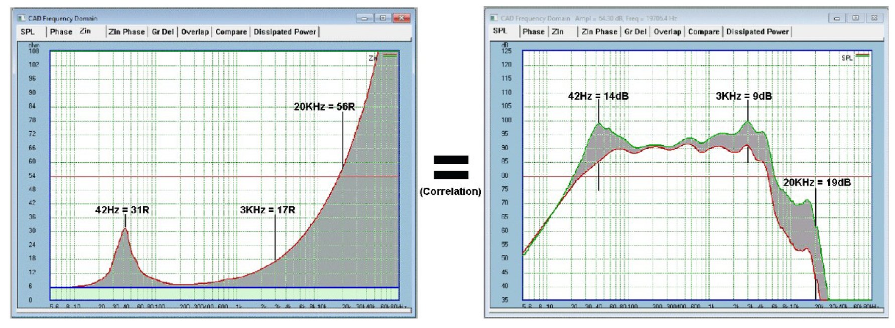
Note on the left, that blue lateral line is the 6R and everything above is some form of back-EMF impedance. So the motional impedance peak at 42Hz is 31 Ohm, but the back-EMF will be 25 Ohm when 6R is subtracted. You can do that any any frequency, but LF is motional back-EMF and higher is inductive back-EMF. At the end I hope we can agree on that.
But let us examine 3KHz:
The impedance nearly triples to 17 Ohm at 3KHz (quite common), then the 1A current is reduced to 353mA, the acoustic output dBSPL, measured with a microphone, drops -9dB.
Ic = 6V/17 = 0.353A
Because the acoustic output dBSPL is proportional to the current:
dBSPL = Log(20)*0.353) = -9dB and that result matches above.
The voltage that appears across Re, we shall call Vre:
Vre = 6R*0.353A = 2.12V
So this has come down from 6V to 2.12V and the 1A current reduced to 0.353A.
Now we can calculate the heat dissipation (there is no heat dissipated in the 11 Ohm back-EMF impedance):
Heat = 2.12V*0.353A = 748mW
So without back-EMF impedance, this would have been 6 Watt, now reduced to a mere 3/4 Watt.
Log(10)*(6W/0.748A) = 9dB
This 11 Ohm back-EMF impedance, being a voltage source and not dissipating heat is interesting. 1) It proves that the dBSPL is entirely proportional to current, not the voltage. 2) The Vre value helps us to understand the dissipation and since most drivers are well below 1%, this means that the dBSPL is also largely, but not exactly, proportional to the heat dissipation.
There are no claims here, this is how it works every day of the week.
But now for something very important to understand, it is this (and this has been approved by some "peers" of note): The imperfections of the driver shows up in the back-EMF impedance of the driver, modulating/changing the current of the amplifier. For example, using the same driver above, if it has a major/bad 3KHz resonance, the bi-directional properties kicks in. At 3Khz that 353mA of current is not a longer stable commodity, now that 353mA is being modulated by a 3KHz resonance because the driver wants to behave like a 3KHz voltage source looking back into the amplifier.
That is just the starting point of research, but so far the maths are solid, and it is clear that further maths and measurements can be developed (they are) based on what the above reveals. Also, note that this distortion shows up on the current side of the amplifier. Don't need to prove that, Pavel's (PMA) measurements have also already shown that. And I told him that. So this is more about what the current side of the WHOLE system is doing, amps and speakers. It is less about the voltage (not excluding what it does) and more about the current.
There is some really serious work done on this right now, it is not about rewriting the rules, it more about understanding the rules that are already there, the physics of it. And cause and effect should be able to explain this, measurements conducted on both the electrical side of the speaker and on the acoustic side (correlation). Cause and effect; we don't need to go quantum or anything - although I do believe and ascribe to the Copenhagen Interpretation for now (I am biased, I was born there).
I intend, with some help, to prove that the solution is in the hands of speaker designers and not amplifier designers. The solution is not current driving, although current drive reveals a number of things that might actually point to making voltage sources work better. Amp designers, relax. 😀
So I hope I have made a reasonable case.
I just spent a good bit of time to present the above. I hope it won't be so glibly dismissed. But it is really is only a synopsis of what is going on.
🙂 Joe
.
Last edited:
You mean the reference level is deifined on the 'tape' as well as the listening level in the studio and the hall ? True.No I'm talking about the fact that they have standards agreed defined and kept to. A film you know is mixed to set levels so (if your neighbours allow) you can calibrate your system and it will be at level deemed correct.
But in such a way that we lose some 10dB of dynamic under the max digital level ! A pity, a shame.
Happily, we can use100% of the digital available dynamic.CDs don't come with a reference level defined on them.
More consistant because... the image ?sometimes the Foley guys have way too much fun but the end result is far more consistent and in some cases more realistic.
The need for localisation is far less important, because the vision prevails. Very often, the distances are not marked in the mix. The voices, on outside scenes (HFmikes, dubbing) sound like in inside: It does not seem to disturb a lot of people. I hate that.
Most of the directors are not so much interested in the sound than the image. Its a pity, because the sound can carry more emotions than images.
In music, we deal with musicians, they know how to listen and what they are talking about.
Not to say that i have not a great opinion about the quality of the work of the majority of the sound recordists during film-shooting. We must weigh that by the fact that they most often can not work in optimal conditions, nobody care, everything for the image.
On my side, I prefer hundred times to record and mix music than movies. (when it is good music). And, i can tell that most of the work, mixing movies, is a secretarial work, choosing between hundreds of tracks, because no one had take decision during editing. Boring.
The thing you hear the most in the editing room is: "We gonna see during the mix."
Last edited:
...I also recommend you read some of Dick Burwen's stuff...If you are not aware of Dick he really can be described as legendary. Anyone with walk in speakers at home has to be taken seriously 🙂
Indeed! After investing many 100's of thousands of dollars in Sonic Solutions and Cedar workstations, I will be honest: I prefer the analog Burwen TNF to all of the de-noising modules in those digital softwares. The very concept of correlating out-of-band noise with surface defects is genius and works really well...if you are willing to adjust it anew with each recording. You retain all of the HF and reverb tails unlike the digital alternatives. It works especially well when you upgrade the op amps in it...
Just my $0.02 worth,
Howie
Indeed.
What do you want ? One speaker by instrument ? Or this nightmare of 5.1 ?
Call it many speakers per instrument and you have the famed Grateful Dead Wall of Sound. 🙂
I went to see them at the Palais des Sports in Paris in the 70's, and almost half a century later, I'm still impressed!
I am not aware of any dynamic range lost. With crest factor taken into account and with headroom for explosions and dinosaur stomps all seems very logical.You mean the reference level is deifined on the 'tape' as well as the listening level in the studio and the hall ? True.
But in such a way that we lose some 10dB of dynamic under the max digital level ! A pity, a shame.
Except 99% of recordings you buy today have almost no dynamic range. The VU meter hangs around -9dB. . 1950s Deccas monos have more DR.Happily, we can use100% of the digital available dynamic.
[/QUOTE]More consistant because... the image ?
The need for localisation is far less important, because the vision prevails. Very often, the distances are not marked in the mix. The voices, on outside scenes (HFmikes, dubbing) sound like in inside: It does not seem to disturb a lot of people. I hate that.
Mainly that the better films (for sound) actually care about the acoustic of the space. May be added in post processing, but you do get a sense of space that many recordings miss. I am unusual and like to feel the room the music was played in. I sit further back in the orchestra hall. Choice and preference for me.
I believe intuition is good.
But the math is anything but elusive. That is the whole point.
We devised an equivalence test based on an 8 Ohm driver…
That is just the starting point of research, but so far the maths are solid, and it is clear that further maths and measurements can be developed (they are) based on what the above reveals.
Joe what you describe is the standard procedure followed when measuring Z with a constant current source. Nothing new, nothing different so far, till:
Also, note that this distortion shows up on the current side of the amplifier. Don't need to prove that, Pavel's (PMA) measurements have also already shown that. And I told him that. So this is more about what the current side of the WHOLE system is doing, amps and speakers. It is less about the voltage (not excluding what it does) and more about the current.
There is some really serious work done on this right now, it is not about rewriting the rules, it more about understanding the rules that are already there, the physics of it. And cause and effect should be able to explain this, measurements conducted on both the electrical side of the speaker and on the acoustic side (correlation). Cause and effect; we don't need to go quantum or anything - although I do believe and ascribe to the Copenhagen Interpretation for now (I am biased, I was born there).
You try again to blur the picture and use the above as a preamble for to substitute cause with the effect and vise versa. Very predictable by now but

a continuous troll, AND unfortunately, again you use other people’s name in it, which is against their stated intention
So the motional impedance peak at 42Hz is 42 Ohm, but the back-EMF will be 36 Ohm when 6R is subtracted.
Per your attachment, impedance peak at 42Hz is 31 Ohm and subtracting 6 Ohm leaves 25 Ohm.
Do you want me to make these corrections on the text?
George
Indeed! It works especially well when you upgrade the op amps in it...
Just my $0.02 worth,
Howie
LOTS of op-amps, I'm not sure that Dick's analog process could not be described by a digital algorithm. IMO it's more that if you start out in a digital mindset you do it a different way. For instance the recursive substitution algorithms for tick and pop removal work far better than the real time analog ones IME and raw available compute power has reduced the latency a lot.
We devised an equivalence test based on an 8 Ohm driver (an actual Peerless 830875 6.5" driver) with an Re = 6R - this is the voice coil resistance.
You show again a speaker with pure voltage vs pure current drive. This has nothing to do at all with a combination of crossover and shunt networks to make a multi-way speaker look like a 6 Ohm resistive load. My take on PMA's results is that you want individual equalized current out amps on each driver to achieve the low distortion performance.
Last edited:
Joe what you describe is the standard procedure followed when measuring Z with a constant current source. Nothing new, nothing different so far, till:
Nothing new indeed, Neville Thiele (you even know who he is?) used this method in the 60's, so I claimed nothing new.
You try again to blur the picture and use the above as a preamble for to substitute cause with the effect and vise versa. Very predictable by now but
a continuous troll, AND unfortunately, again you use other people’s name in it, which is against their stated intention
Please make sense of that, because I can't. It just seems you show animosity with cause. Why?
Per your attachment, impedance peak at 42Hz is 31 Ohm and subtracting 6 Ohm leaves 25 Ohm.
Do you want me to make these corrections on the text?
George
Correct, it is indeed 25 Ohm. I made a typo/error, that happens sometimes and nobody is perfect. Thank you for the correction.
Now please do the maths for 42 Hertz and 31 Ohm where the Re DC resistance is 6R. The maths works there the same as it does for the calculations that I showed with the example of 3KHz. The math works and I would love you to pay attention to that.
May I ask, please don't play the man, but the ball (a football analogy), then we will have a chance of being on the same page. That way I can't be called a troll, and a troll is somebody who intends to be a troll, I have no such motive. OK?
You show again a speaker with pure voltage vs pure current drive. This has nothing to do at all with a combination of crossover and shunt networks to make a multi-way speaker look like a 6 Ohm resistive load...
I left the crossover out for simplicity's sake, the crossover introduces a number of other variables, and they are not unimportant. But the crossover needs to suppress the current modulations of distortion products (I used a 3KHz resonance as an example) and you can indeed do that. But that is a separate but related topic. A single driver is best when you have a problem (like that 3KHz resonance).
My take on PMA's results is that you want individual equalized current out amps on each driver to achieve the low distortion performance.
No, I suggest you read what I posted more carefully. I particularly spoke about voltage sources, not current sources. I am in the voltage source camp rather than current. Please, at least make an effort and read it again and you will see that. OK?
Last edited:
You were ok to here. But you jumped the rails.Hi Mark, back again. I realised the above needed to commented on: You say it "looks" like an impedance but you say it is not. I hope you don't mind if I now make a case for it being exactly that, an impedance, but not a resistive one, obviously, but one that impedes current nonetheless.
I believe intuition is good.
But the math is anything but elusive. That is the whole point.
We devised an equivalence test based on an 8 Ohm driver (an actual Peerless 830875 6.5" driver) with an Re = 6R - this is the voice coil resistance.
The microphone was calibrated to read high accuracy dBSPL.
Two amplifiers are needed, a voltage source and a current source.
This is the two results:
Note on the left, that blue lateral line is the 6R and everything above is some form of back-EMF impedance. So the motional impedance peak at 42Hz is 31 Ohm, but the back-EMF will be 25 Ohm when 6R is subtracted. You can do that any any frequency, but LF is motional back-EMF and higher is inductive back-EMF. At the end I hope we can agree on that.
But let us examine 3KHz:
The impedance nearly triples to 17 Ohm at 3KHz (quite common), then the 1A current is reduced to 353mA, the acoustic output dBSPL, measured with a microphone, drops -9dB.
Ic = 6V/17 = 0.353A
Because the acoustic output dBSPL is proportional to the current:
dBSPL = Log(20)*0.353) = -9dB and that result matches above.
The voltage that appears across Re, we shall call Vre:
Vre = 6R*0.353A = 2.12V
So this has come down from 6V to 2.12V and the 1A current reduced to 0.353A.
Now we can calculate the heat dissipation (there is no heat dissipated in the 11 Ohm back-EMF impedance):
Heat = 2.12V*0.353A = 748mW
So without back-EMF impedance, this would have been 6 Watt, now reduced to a mere 3/4 Watt.
Log(10)*(6W/0.748A) = 9dB
This 11 Ohm back-EMF impedance, being a voltage source and not dissipating heat is interesting. 1) It proves that the dBSPL is entirely proportional to current, not the voltage. 2) The Vre value helps us to understand the dissipation and since most drivers are well below 1%, this means that the dBSPL is also largely, but not exactly, proportional to the heat dissipation.
There are no claims here, this is how it works every day of the week.
The 42 hz is a resonance, a 3khz resonance is the exact same mechanism as the 42 hz. You cannot change the "properties" as you wrote.
If your "peers of note" agree with your description, you need better peers.
I would be happy to explain this to the people you consider experts so that they may understand.
John
May-be we were sitting side by side ?Call it many speakers per instrument and you have the famed Grateful Dead Wall of Sound. 🙂
I went to see them at the Palais des Sports in Paris in the 70's, and almost half a century later, I'm still impressed!
The problem was, from the place were I was, that the surface of each instrument speakers was so huge that it produced a incredible directivity and a comb effect. Even far from the scene, I was able to change the mix by slightly moving my head. Up to erase totally an instrument.
My neck hurt at the end of the concert.
No intermodulation, very low distortion, nothing between the musicians and the audience, an incredible look with this black transparent curtain and this incredible number of Studio JBL monitors, the bluish light of those hundreds of Macintosh amps ... It was, indeed, a shock for me too.
So innovative !!!!!
And this incredible clarity in a hall impossible to P.A. with all the long echoes it produces usually...
Je me suis demandé quelle était la marque de la moquette qu'ils devaient fumer.... ;-)
It's funny to think that J.C (hat off) was part of one of those crazy genius. This idea to set two mikes in phase opposition to reduce the larsen !!!!
And funny to think that i'm talking to an other survivor dinosaurus drinking at the exact same water point a few million years ago.
Last edited:
You were ok to here. But you jumped the rails.
The 42 hz is a resonance, a 3khz resonance is the exact same mechanism as the 42 hz. You cannot change the "properties" as you wrote.
Hi John, I don't think you understood the subject. Please read what I posted more carefully.
.
But the crossover needs to suppress the current modulations of distortion products (I used a 3KHz resonance as an example) and you can indeed do that.
I doubt it. It's very easy you have a microphone, measure the distortion of your Elsinore speaker and see how it compares to true current drive on the same drivers. (what PMA did).
I spoke only to PMA's comment asking you not to imply he agrees with you.No, I suggest you read what I posted more carefully. I particularly spoke about voltage sources, not current sources. I am in the voltage source camp rather than current. Please, at least make an effort and read it again and you will see that. OK?
You also continue to use confused terminology EMF and impedance don't even have the same units, they are not equivalent. If you want to use math please use complex algebra and do it right. Using Ohms without phase just ends up making things wrong.
Hi John, I don't think you understood the subject.
You have to be kidding.
Joe Rasmussen, sorry to say this, but I fear Scott is right. EMF is a power source (P), Impedance, the load (R).You also continue to use confused terminology EMF and impedance don't even have the same units, they are not equivalent.
As long as V=RI, P= RI² or V²/R, as you prefer.;-)
Last edited:
- Status
- Not open for further replies.
- Home
- Member Areas
- The Lounge
- John Curl's Blowtorch preamplifier part III