B&K has a new device with tuned ports to measure HD of microphones. https://www.bksv.com/~/media/literature/Product Data/bp2105.ashx
Gumout spray carburetor cleaner will usually dissolve the loudspeaker glue, allowing you to take apart a loudspeaker driver and reassemble it later. Of course don't breathe the fumes.
What appears to be ignored here is that a condenser microphone is a relatively PREDICTABLE device, compared to a power amp, for example. This is because all the elements, capsule, electronics and even transformers mostly (if used) are fairly predictable with different levels, AND the electronics can be measured separately from the capsule, (essentially) by just using a dummy cap for an input of the same capacitance as the microphone capsule, to make measurements easier. What I am trying to point out here is that IF you can measure at one particular level, then mathematically you can PREDICT the distortion generated at any other level (mostly) due to the fact that the whole system is based on a Class A transfer function. No Xover distortion here! Now, it is difficult to get a single loudspeaker clean enough to give you a really accurate reference, so alternative methods are often used. Still, a pro capsule like a B&K can be used as a reference, then another mike capsule can be compared to it even with a simple speaker test, because the pro capsule will be designed to be so much better than any speaker that I know of, at least. If the measured distortion of the two mikes is about the same, then the cheaper mike is probably OK for limited testing of loudspeakers themselves.
Pavel, how about this. Do a 200Hz single tone THD test, calibrated to frequency response and phase. Then post the calibrated .wav file. Say 60 seconds. Since magnetic distortions follow input phase, we should be able to deconstruct the residual into harmonics and that will show us where on the wave the nonlinearities occur.
Hi keantoken,
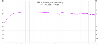
another quiet morning, so I did the 200Hz >1 minute measurement, the link is
http://pmacura.cz/w18.zip
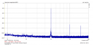
Legend: the file is stereo, 44.1/16. It starts with "silence". Left channel is microphone record of the 200Hz tone from W18NX001 woofer, measured nearfield, 1.4V at woofer terminals. Right channel is the electrical 200Hz excitation signal. So you can directly read time delay between acoustic and electric paths.
Because of the nearfield measurement, with the 6.5" woofer, the data make sense to some 700Hz. So please restrict the analysis to H2 and H3. The W18NX001 distortion at 200Hz/1.4V is pretty low, like 0.06%. Dynamic range of measurement is high, so we can see even very low level details and also noises of transformers of appliances etc.
I have the REW measurements saved, so, I can link them in the PM, if needed.
(Yes the power amp used is the class A sub 0.001% distortion)
Attachments

find a link to an old "Chat With Harvey (Gerst)" for a run down on various mics.
Is this OK?
RMMGA/RAP postings on mics for recording/amplifying acoustic guitars (2001)
I’m more certain about this one (jn)
YouTube
To use it properly, I would ground one end, …
It’s the proper moment to use your pencil to sketch it for us, John
George
True, the response irregularities don't matter much for distortion. But the FR can be extremely off both at HF and at LF (see this german site where hundreds of various type microphone calibrations are logged).It changes, but I see no reason for it being less controlled. It would need recalibration not easily done by the user. For low frequency distortion measurement I see no material changes.
--------------------------
While looking for info about the Transsound capsules I just found this very interesting page for preamps/buffer: A
potentially novel pre-amp for electret mic capsules which have their
internal FET's Drain and Source connections available separately, I have to admit that I don't fully understand the circuit at first sight but it might be another, better way to extract the gate voltage with lower distortion (and noise, hopefully) than the standard follower (even when Id and Vds are held constant). Any comments?
Maybe cheaper compression drivers are an option for testing because they are designed to have user-replacable diaphragm assemblies and everything is quite large in terms of dimensions.Tomorrow I'll grab three or four tweeters, I think they are 3/4 domes. I'll pull one or two apart, see if I could wind a pickup half coil on it.
That would be interstitial on one layer. To use it properly, I would ground one end, put the other into a summing node at gain of 2, subtract it from the drive coil voltage, output being the effective diff.
Plus, a tweeter really doesn't need tinsel.
find a link to an old "Chat With Harvey (Gerst)" for a run down on various mics.
Maybe this one Scott?
Attachments
B&K has a new device with tuned ports to measure HD of microphones. https://www.bksv.com/~/media/literature/Product Data/bp2105.ashx
Again, as usual, their distortion plots end at -60dBrel. We are talking much lower distortion of microphones, here, and even speakers. I am not sure if anyone in the industry is interested in values below 0.1%.
T, these people are not interested in understanding. They find making you look 'incorrect' more satisfying.
Now let's talk about differences between condenser and dynamic mikes.
One of the major differences is phase.
Dynamic mikes deliver max output at zero crossings, condensors at max excursion. Therefore, you cannot mix the two types when miking an instrument (book knowledge, don't know how it pans out in real life).
Again, as usual, their distortion plots end at -60dBrel. We are talking much lower distortion of microphones, here, and even speakers. I am not sure if anyone in the industry is interested in values below 0.1%.
Some more informations are included in the mentioned ICA-paper:
https://www.icacommission.org/Proceedings/ICA2004Kyoto/pdf/Mo4.E.2.pdf
What appears to be ignored here is that a condenser microphone is a relatively PREDICTABLE device, compared to a power amp, for example. This is because all the elements, capsule, electronics and even transformers mostly (if used) are fairly predictable with different levels, AND the electronics can be measured separately from the capsule, (essentially) by just using a dummy cap for an input of the same capacitance as the microphone capsule, to make measurements easier. What I am trying to point out here is that IF you can measure at one particular level, then mathematically you can PREDICT the distortion generated at any other level (mostly) due to the fact that the whole system is based on a Class A transfer function. No Xover distortion here!
It seems to be the default assumption thoughout this thread that the world is slightly non-linear but monotonic. You've raised the topic several times to deafening silence.
Keep trying. Thanks, Chris
Again, as usual, their distortion plots end at -60dBrel. We are talking much lower distortion of microphones, here, and even speakers. I am not sure if anyone in the industry is interested in values below 0.1%.
Not really, if you read their tech articles the lines follow theory (simple polynomial expression) extremely well at low SPL and extrapolate (especially 2nds) far below the bottom.
EDIT - I see that has already been noted.
Last edited:
Some more informations are included in:
Frederiksen, Erling. System for Measurement of Microphone Distortion and Linearity from Medium to Very High Levels
https://www.bksv.com/media/doc/bv0055.pdf
Frederiksen described one mechanism which leads to departure from the prediction wrt H2 for some microphones.
Frederiksen, Erling. System for Measurement of Microphone Distortion and Linearity from Medium to Very High Levels
https://www.bksv.com/media/doc/bv0055.pdf
Frederiksen described one mechanism which leads to departure from the prediction wrt H2 for some microphones.
Just last week I went through the company's inventory of 200+ dynamic and condensor microphones, tightening earthing screws, cleaning/lubing mounting clip threads and checking operation (vocal check).
There is great (huge) range of performance in terms of sensitivity, frequency response, dynamics and clarity with AKG and Telefunken/Neumann the standouts. In addition all microphones makes/models responded very favourably to my 'treatment', especially passive dynamic Shure models with internal matching transformer, but also all condensor types....sensitivity and clarity increases markedly.
Headphones, a decent preamp and a simple 'check, one two' tells much about microphone performance.
Also, placing a dynamic mic in front of speaker cone/VC is certain to pick up magnetic modulated 'beam' as I described in an earlier post.
Dan.
Some more informations are included in the mentioned ICA-paper:
https://www.icacommission.org/Proceedings/ICA2004Kyoto/pdf/Mo4.E.2.pdf
Thank you!
Frederiksen described one mechanism which leads to departure from the prediction wrt H2 for some microphones.
Yes, the passive shunt capacitance of the preamp matters on the small capsules. Your first link showed graphs that went down to the noise limit of the instrument for the large capsules and they looked pretty well behaved. The pre-amp that Jan built for the Triode fest has the capability of implementing Mr. Frederiksen's negative capacitance technique. I never had any way of verifying it with an actual mic just with an actual source capacitance.
- Status
- Not open for further replies.
- Home
- Member Areas
- The Lounge
- John Curl's Blowtorch preamplifier part III