Keantoken, here is the repeated 250+250Hz IM measurement, voltage drive, 1.4Vrms. I am attaching not only plots, but also a zip file that contains a txt export from REW of the spectrum plot.
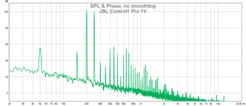
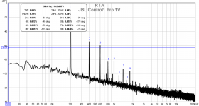
I would like to add one more measurement of 200+250Hz IM distortion, now with much worse speaker - JBL Control1 Pro. It is measured at 1Vrms at speaker terminals, more voltage would bring too much components related to case buzz etc.
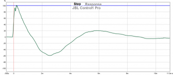
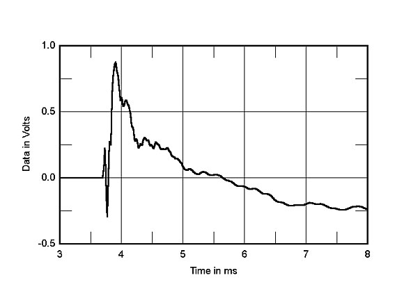
We can see that distortion spectrum has a lot of high order harmonics, which is confirmed by a measurement at 200Hz single tone. Attached is also a step response, especially for JC. It is almost optimal, isn't it? 😀
--------
More in general to speaker nonlinear distortion contributors:
1) E/M is the only part of it and almost sure not prevailing,
2) spatial radiation of acoustical output side is maybe most important,
3) inherent partial vibrations of membrane
4) irregulaties of the non-linearity depending on frequency,
5) distortion due to Doppler effect.
Attachments

Last edited:
More in general to speaker nonlinear distortion contributors:
1) E/M is the only part of it and almost sure not prevailing,
2) spatial radiation of acoustical output side is maybe most important,
3) inherent partial vibrations of membrane
4) irregulaties of the non-linearity depending on frequency,
5) distortion due to Doppler effect.
1: A reason to avoid improve-it, if we can do-it in a simple way ?
2: This is the first thing that catches you when you listen to a recording of the acoustical output of a speaker assembly. And all the hard work your brain has done to erase so much of its effect.
3: No huge improvement with all the attempts to find better material than the "paper" used since the beginning to build speaker's membranes, no ?
4: Same remark then 2.
5: I could add the non linearity of the air compression.
And, as J.C. pointed out, the importance of the linearity of group delays. This can be corrected, aligning the speakers in multi-ways systems, or using digital delais to flatten-it. I don't understand why this is still neglected by so many speaker's designers.
PMA
While we agree...
When I took training on repair and maintenence of a 250k semiconductor test system, there were procedural rules that were NEVER to do ignored. EVER!!!!
1. Check all the power supplies. If any one of them (I think there were four or five). Did not meet any of their specifications, fix them. Do NOT attempt to troubleshoot anything else until all the supplies meet their specifications. EVER!!
2. If after fixing the supplies there is still a problem, fix it.
Very seldom was step 2 required. Even though the apparent problems varied, it was rarely the analog stuff.
In the case of speakers, the force which moves the cone is the primary driver. If the magnetic drive is creating harmonics and intermodulation of the forces which push the cone;
2. Spatial radiation patterns will not remove them.
3. Inherent partial vibrations oo membranes will not remove them.
5. Doppler effect or lack thereof will not stop it.
Think of this problem as you would your own personal stereo. If you find your cart is mis-tracking, do you band aid your preamp, or reposition your speakers?
Surely you could characterize the distortion and apply some DSP.
If one of your spark plug wires is disconnected, would you play with tire pressure to fix mileage?
We, including you, have confirmed that a speaker's variable magnetics distort the current, creating H2, H3, as well as much intermodulation products. And none of this is due to the other factors you mention. You espouse current drive to get around this magnetic non linearity, not fix it.
I want to fix it. Get as far as we can to that end, then let everybody else attack the balance of the issues as you mention.
Jn
improve-it, flatten-it....
Your use of hyphen is a bit unorthodox. Should I pay attention to them in the sense that they have indeed a specific semantic meaning to be understood? I'm asking since I sincerely would like to understand what you signal.
//
Last edited:
The purpose of the pickup coil is to ignore all the magnetic effects in the structure which communicate to the coils. Being co-wound, they will both see the exact same magnetic flux. By subtracting the pickup voltage, what is left is the non flux related voltage of the drive coil.Its not calibrated but the drive is about 1v and the fundamental amplitude is less than 100.mV. The 2nd harmonic is 40+ dB below that, 1 mV. So you are looking a low level stuff with only.7 or 8 averages.
I wanted to confirm I'm on the right track before doing a lot of testing.
Next round will be more formal.
Entities which are magnetic and will cancel out: the reactive stuff.
Inductance of the magnetic circuit, including any change in that inductance.
Inductance of the voice coil including any change in that inductance.
Any reactive effects caused by voice coil position or velocity, underhung, overhung.
Entities which will remain in the difference; the resistive stuff.
IR drop of the current in the voice coil. This includes resistive modulation caused by proximity effect.
Dissipation cased by the eddy losses of all conductive surfaces impacted by the primary field of the drive coil.
What remains to be understood and looked at:
When a former is dragging through the the gap, it pulls the gap flux by exclusion (recall that "magnetic diode" discussion a few months ago; they had some great FEA's showing how the copper was pulling the dipole field in the direction of rotation). This will reduce the gap field, and this is common to both coils. I suspect this is a cause of some IM distortion, and may be seen in the diff.
Eddy braking of a conductive former is real and directly proportional to velocity. It will dissipate most at center of gap position as that is where velocity is highest. Because it is fighting motion, in V drive mode it will increase drive current because the EMF is lower. This will show up in the difference due to IR drop. I think it will be a distortion because in essence it is a position based loss, but have to think more on that. It would be a very soft clip in the velocity waveform.
Eddy braking of the copper of the coil, not sure if the copper diameter is sufficient so plan on testing that. But same class as former.
Iron saturation and hysteresis affect both coils, so I would expect those effects to be subtracted from the diff. That is in fact why I developed this technique.
Finding how the diff sees V and C drive, what the diff distortions are, how the system reacts to diff drive, how we can use diff pickup as a diagnostic, all unknowns..
As you can see, there are as many unknowns as knowns. That is what makes this so much fun.
Cheers,
John
If it's anything like my I-pad.... I spend half my time fixing what this infernal thing changes my typing to.Your use of hyphen is a bit unorthodox. Should I pay attention to them in the sense that they have indeed a specific semantic meaning to be understood? I'm asking since I sincerely would like to understand what you signal.
//
Jn
With a cone loudspeaker system the harmonic distortion sound power is reduced by the cone mass and diameter induced directivity. So one issue with a real woofer is does the motor's harmonic distortion increase with frequency? That may not be as much of an issue then.
Pavel,
The JBL Control 1 Pro last I knew was made by a Chinese contract manufacturer. If it is the one I know about their sales representative was quite cute and not an engineering specialist. Decisions, decisions & low price.
In practice I can spend over $100 dealer price on a JBL Control 1 or $17 on another Chinese made house brand product that is on a recommended list.
Last edited:
... or $17 on another Chinese made house brand product that is on a recommended list.
Hey simon7000, any link on that one? I'm looking for a cheapy for a computer. Thanks.
Stereophile list from Parts Express. Posted about it here before. When in my office I can retrieve model number.
Yes, I am yet to meet 1960+ model German's who do not speak perfectly good English.Max, On reasonably good terms with the D & B Audiotechnik guys. I find it quite impressive as to how well they speak English. They have done custom loudspeakers for a project of mine. Went so far as having one of their Backnag guys stop by to visit. Showed him the small town where my shop is located. It was built by German settlers and follows that architecture style.
Their web site gives sales oriented of course quite good info regarding the company and products ethos.
Inside and out their amplifiers and speakers are very well/thoroughly engineered, and reliability and performance is good, very good.
Dan.
Last edited:
Stereophile list from Parts Express. Posted about it here before. When in my office I can retrieve model number.
Probably the Dayton B652. Good enough for me, but maybe not for John Curl 🙂
I'm interested.The instantaneous frequency of a narrow-band signal can be determined by the so-called parametric spectral analysis, i.e. by a simultaneous analysis of the signal in the time and frequency domains.
If there is interest I can present an example.
Regards,
Braca
Is this related to wavelets? I've read about wavelets but I haven't quite got my head around the concept and how to use it.
Linkwitz on his site mentioned bursts and tonebursts for testing speakers, I don't know if he intended that to be the same thing as wavelets, but it sure looks similar.
I'm interested.
Is this related to wavelets? I've read about wavelets but I haven't quite got my head around the concept and how to use it.
Linkwitz on his site mentioned bursts and tonebursts for testing speakers, I don't know if he intended that to be the same thing as wavelets, but it sure looks similar.
And please...not by PM...
I'm interested as well.
Jn
oddly those daytons hit our shores at £64 a pair, which is getting close to a lot of manufacturers basic models.
$30.88 + $6.95 shipping is good... £64 + whatever shipping is not good. Think I stay with my ESL57, but they're at the end of the corridor, 2 rooms down 🙁
I bought some previously, and they were so good (at the price) I bought
more this Xmas and gave them away as presents.....

more this Xmas and gave them away as presents.....
I bought some previously, and they were so good (at the price) I bought
more this Xmas and gave them away as presents.....
So do you give XA25's with $30 pairs of speakers? 😛
Thank you for the heads up. I just ordered four pairs and paid $130 including tax and shipping.
_
_
Attachments
Last edited:
- Status
- Not open for further replies.
- Home
- Member Areas
- The Lounge
- John Curl's Blowtorch preamplifier part III