Thanks.
I'm with jn, If I can't communicate that I'm sorry and this stuff is trivial in the stream of things then I'm truly sorry.
Joe,It wan't my claim, but one I understand. <snip>
Thank you for providing more info. As others can provide, the circuits are capable of tens of MHz response, far beyond simple measures. What is important is, is the response producing something we can hear. 2 percent... Nah.. .1% is the minimum..
I'll be quiet for five days, but I cannot stop thinking. See you in a few..
Jn
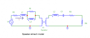
A speaker has many reasons to be a nonlinear load even if the cone is locked. The current is an analog of both the force in the gap and any magnetic nonlinearities in the magnet structure.
You can use feedback around the system, e.g. sensing the cone, but the prop delay makes it unusable above several hundred Hz. In headphones the best is around 2KHz.
You can use feedback around the system, e.g. sensing the cone, but the prop delay makes it unusable above several hundred Hz. In headphones the best is around 2KHz.
I'll be quiet for five days, but I cannot stop thinking. See you in a few..
Jn
40 days, 40 nights as it is written.
A speaker has many reasons to be a nonlinear load even if the cone is locked. The curren is an analog of both the force in the gap and any magnetic nonlinearities in the magnet structure.
You can use feedback around the system, e.g. sensing the cone, but the prop delay makes it unusable above several hundred Hz. In headphones the best is around 2KHz.
Well, duh.
My cabbage friends all agree with you.
My forte would be the magnetic thingy..
However, When I get back, I'm gonna look into the bandwidth of the renishaw encoders for driver positional feedback. Yah, they may be 7K per unit, but this is audio, right?? No expense spared??
Jn
40 days, 40 nights as it is written.
I thought it was " wasted days an wasted nights"..
Jn
but using 0R1 current sense resistor will have greater resolution.
I only have a good feeling, but the 1R test is rough and ready, yet it points the way. So time, please, and more than one person will be doing the test, that is the idea, an icon for your message from the following list:
No icon and reach consensus.
Cheers, Joe
<snip>
I have also seen thd be higher doing similar tests many years ago. Seems to be related to the back-emf.
-Rnm
Last edited:
I have couple of inexpensive position sensing solutions that work for this. I'll post them tomorrow.Well, duh.
My cabbage friends all agree with you.
My forte would be the magnetic thingy..
However, When I get back, I'm gonna look into the bandwidth of the renishaw encoders for driver positional feedback. Yah, they may be 7K per unit, but this is audio, right?? No expense spared??
Jn
(multiple snippages throughout).
[or was that just the schtick of the conductor's baton.]
Cheers,
[Is he wearing a metal suit or just moving a white metal stick?]....The conductor spins, the magnetic field is dragged in the direction of rotation.
[or was that just the schtick of the conductor's baton.]
[maybe the fluid in the ears helps with the musical experience, it could be orgasmic in intensity, have you ever seen a great conductor in person?].Here however, is the crux:
Quote:""
...the conductor experience as they move...
[By flailing their arms about]....the conductor is generating eddy currents.
[Will the ensenble watch a "still conductor" or will the perform of their own accord? The educated named the force pulls him/her to the earth's center gravity. Gravitas--in politiceese. ]...In a still conductor with current, the conductor will have forces.
Cheers,
Last edited:
So much debate and heckling about what is actually a very simple matter......what Joe and co are documenting is the effects on typical amplifiers of reactive loading, and suitable remedy. By 'impedance equalising' the loudspeaker system to resistive characteristic, there is no return energy that the amplifier has to quench/deal with and this is where the subjective benefits start. Typical amplifier Damping Factor is not constant over frequency/amplitude/history and this gives rise to amplifier reactive load dependency and consequent set of subjective findings.
It's a simple as that !.
Dan.
It's a simple as that !.
Dan.
Except it's not a suitable remedy, especially with a passive crossover. That's the issue at play.
What I am pointing out is that (and the idea is getting traction) is that the reduction in distortion under current drive is because the amplifier cannot produce reactive current. But under voltage drive, the amplifier readily produces reactive current. So the increased distortion we see (and the measurement can easily be repeated) is due to amplifier reactive current drawn by the back-EMF impedance of the driver.
Sorry, completely wrong. It is the complex load nonlinearity that creates the distortion seen. In case of linear complex load, there is no distortion - attached. "Back EMF" view is a nonsense.
Attachments
His work could be as simple as you said, but not enough was shown and his explanation defies understanding !!!???... 😕...It's a simple as that !...
As I promised earlier, position servos. Both easier and cheaper than the Renishaw encoders. Also with digital encoders you will have some challenges with delays and finding the rest point. Keyance also has encoder/position sensing solutions. They work to pretty high frequencies. And for something like a speaker these are a possibility: Vibration Sensors & Probes | Fiber Optic MTI 2100 Fotonic Sensor | Ultrasonic Transducers (I have a couple and they work pretty well to above 20 KHz but not easily implemented in a speaker. However. . .)
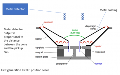
Attached are two position servo solutions I have used commercially. Both work. As John has said implementation is not trivial.
The first uses a metal detector to sense the metallized cone. Its output is proportional to the distance from the metal. It also works with metal voice coil formers. However it can be sensitive to various noise sources.
The second uses a coil to create an ultrasonic magnetic field around the voice coil. A detection circuit measures how much of the ultrasonic field is picked up by the voice coil above the gap. The gap acts as a shield preventing the coil below the gap from picking up the field so the HF on the coil is directly proportional to the position (or projection) of the voice coil. Its distantly related to an LVDT, linear variable differential transformer, LVDT Tutorial | LVDT Basics - What is an LVDT | TE Connectivity which would also work but much harder to implement in a speaker.
Attachments

So much debate and heckling about what is actually a very simple matter......what Joe and co are documenting is the effects on typical amplifiers of reactive loading, and suitable remedy. By 'impedance equalising' the loudspeaker system to resistive characteristic, there is no return energy that the amplifier has to quench/deal with and this is where the subjective benefits start. Typical amplifier Damping Factor is not constant over frequency/amplitude/history and this gives rise to amplifier reactive load dependency and consequent set of subjective findings.
It's a simple as that !.
Dan.
Its not as simple as you think and nothing Joe has stated is anything new. Philips and Panasonic were aware of these issues since the late 60's. This is why they came up with Motional Feedback for loudspeakers.
Read about the Panasonic solution here
Philips wrote a paper about it. Read PDF here
JBL were also aware and spent engineering time designing new motors, Lots of info in their technical notes like the one attached.
Some interesting discussion here about the same topic: Faraday ring in louspeaker driver, what is it?
Attachments
How 'bout use DVC driver ..... 1 VC as usual ..... other as pickup coil ?As I promised earlier, position servos. Both easier and cheaper than the Renishaw encoders. Also with digital encoders you will have some challenges with delays and finding the rest point. Keyance also has encoder/position sensing solutions. They work to pretty high frequencies. And for something like a speaker these are a possibility: Vibration Sensors & Probes | Fiber Optic MTI 2100 Fotonic Sensor | Ultrasonic Transducers (I have a couple and they work pretty well to above 20 KHz but not easily implemented in a speaker. However. . .)
Attached are two position servo solutions I have used commercially. Both work. As John has said implementation is not trivial.
The first uses a metal detector to sense the metallized cone. Its output is proportional to the distance from the metal. It also works with metal voice coil formers. However it can be sensitive to various noise sources.
The second uses a coil to create an ultrasonic magnetic field around the voice coil. A detection circuit measures how much of the ultrasonic field is picked up by the voice coil above the gap. The gap acts as a shield preventing the coil below the gap from picking up the field so the HF on the coil is directly proportional to the position (or projection) of the voice coil. Its distantly related to an LVDT, linear variable differential transformer, LVDT Tutorial | LVDT Basics - What is an LVDT | TE Connectivity which would also work but much harder to implement in a speaker.
Except it's not a suitable remedy, especially with a passive crossover. That's the issue at play.
It's a two-step thing. Yes, the passive crossover can be both a problem and a blessing. The whole thing is about finding a remedy, you are spot on about that. The more series impedance you have with the back-EMF impedance of the driver, the more it will be suppressed, but the key word here is series because it forces the impedance upwards (step 1) and that make the EQ of the amplifier much easier to do (step 2). So the crossover can work in your favour. This is exactly how the Elsinore Project DIY speakers works. But to do a crossover this way is a leap of faith because in your mind you have to change your priorities.
Please see attacments below.
EL-6: DIY speakers.
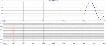
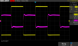
EL-6 Voltage (yellow) versus Current (purple) of the amplifier when driving EL6 speakers.
EL6: FR using Current drive (green) versus Voltage drive (Red).
EL6: EQ of Vented Bass alignment, but Sealed alignment can be made better still.
Note that when forcing the amplifier to produce the same current at all frequencies, the output impedance effectively becomes cancelled out. Even the crossover no longer needs to see a zero Ohm impedance. On the surface, as Scott alluded to, the explanation is a la Thevenin (a voltage model), but a closer look this is purely about how the current is dealt with and gives a much more clearer picture.
Final attachment: What a typical 2-Way crossover and EQ might look like.
Attachments

I have also seen thd be higher doing similar tests many years ago. Seems to be related to the back-emf.
-Rnm
Absolutely!
Running over the same point again and again. How many times?
Last time you hit it on this same thread, was April
Joe,
We do know that you are working on it for a long time.
Your newest thread on the same topic. Never give up ?
Back-EMF and flat impedance
George
I have a suggestion.
Last time you hit it on this same thread, was April
Hear, hear!
Joe,
We do know that you are working on it for a long time.
Your newest thread on the same topic. Never give up ?
Back-EMF and flat impedance
George
- Status
- Not open for further replies.
- Home
- Member Areas
- The Lounge
- John Curl's Blowtorch preamplifier part III