Does anybody recall any amplifier stability papers where this behaviour was evident?
Gee if Joe's amplifier looks like that all bets are off.
After some time, I reduced the gain and the instability stopped.
That's counter-intuitive, usually lowering closed loop gain makes things more unstable. I confess I still poke around breadboards with my fingers to find "anti-G" spots to try to find a place for a little C to be applied.
Does anybody recall any amplifier stability papers where this behaviour was evident?
I do.
jn
You can make an amp that oscillates at zero but is stable at clipping. It usually doesn't look quite like that though. It's too symmetrical. But maybe it is a class A amp with a non-complimentary output stage (which can behave with better symmetry than complimentary).
The oscillation is chaotic though, which is very unusual. Maybe you accidentally created a parasitic bistable circuit. Or perhaps it is picking up a radio station while acting like a superregenerative receiver, and that is causing the modulation.
It could also be some kind of computation noise if this is a simulation.
Does anybody recall any amplifier stability papers where this behaviour was evident?
I had made an LM3886 guitar amplifier for my younger daughter.
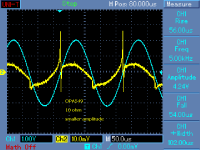
It showed such unstable behaviour around the zero crossing. Excellent acoustic effect.
Never understood why it behaved like that.
After some time, I reduced the gain and the instability stopped.
This can be easily found by forcing current to the amp output. Avoid power chipamps and underbiased class AB.
George, feedback reduced the issue, but did not cure it completely.
Attachments
Last edited:
I have a suggestion.
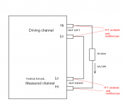
What a voltage source does on the current side and that current through a voice coil is what makes the dB-SPL happen, a measurement is being developed right now that will compare the voltage (reference) to current (what makes the sound) and I am optimistic that this might show something up because they will be different.
Yea it's called impedance? That test has been around for 100 years!
Yea it's called impedance? That test has been around for 100 years!
Joe still does not understand that shunting an ideal voltage source with an impedance does not change the fact that it still looks like 0. I said before someone with a badly designed amplifier might get better sound from speakers designed his way but there is nothing new there (uA741's don't work for audio, so what).
Last edited:
You can make an amp that oscillates at zero but is stable at clipping. It usually doesn't look quite like that though. It's too symmetrical. But maybe it is a class A amp with a non-complimentary output stage (which can behave with better symmetry than complimentary).
The oscillation is chaotic though, which is very unusual. Maybe you accidentally created a parasitic bistable circuit. Or perhaps it is picking up a radio station while acting like a superregenerative receiver, and that is causing the modulation.
It could also be some kind of computation noise if this is a simulation.
It was not a simulation. It was a single motion controlled stage.
The hash as it were, is just a consequence of the servo update rate, 2.25 Khz. Note the motion is a .2 hz sine.
What is important is that the oscillation occurs when the velocity is constant. What this means for the system I am driving, is that the magnetic forces are minimum. If you take a controlled position system and push against the drive, the spring constant of the motor changes. It becomes stiffer the more you resist.
For speakers, this is consistent with acceleration of the cone and hardness of the air resisting the cone movement. Through an entire 360 degrees of sine voltage, the acceleration of the cone (and hence the stiffness provided the amplifier) is a dynamically changing entity.
The softer resistance of the cone and air is during the constant velocity portion of the cone movement. This is exactly what my plot showed.
If you create a simple electrical model of a speaker using masses and springs, to calculate the springs you need to consider the acceleration. Of course, that changes over the cycle.
If you look at a speaker real/imaginary resistive plot, you can see that the constant velocity motion has a variable phase relationship to the drive signal. This gets considerably worse when it's a 3 way with crossover.
George, I'll try to find the papers. I recall one was Cyril Bateman, but he was showing bursts at peaks, and it was not apparent from his models if it were a result of the model simulation constant load velocity at the peaks.
jn
to wit: As far as I can find, it has always been assumed that the speaker load is a linear entity for the purposes of phase margin in a negative feedback system. It is not.
Last edited:
This can be easily found by forcing current to the amp output. Avoid power chipamps and underbiased class AB.
George, feedback reduced the issue, but did not cure it completely.
This is probably happening because as the amp under test passes through zero, the devices are 'almost off' and will actually be off in an under biased class AB amplifier. So, during this period, there is notging sinking the driving amp output current, so it spikes up or down.
If you increase the feedback, the dead zone will narrow - decrease feedback it should open up.
If you decreased the amplifier gain, the loop gain would increase, and the spiking across would decrease.
I would imagine with a reactive load, a system with insufficient gain/phase margin could misbehave.
Just a thought.
It was not a simulation. It was a single motion controlled stage.
The hash as it were, is just a consequence of the servo update rate, 2.25 Khz. Note the motion is a .2 hz sine.
Your idea to modulate the compensation to track the phase modulation of the system is probably an idea everyone who's wrestled with stability has thought about. However the compensator corner frequency is closer to the signal frequency than the corner frequency of the system which is wandering. This means that modulating the compensator frequency will cause a larger error signal than the system's own phase distortion. So you may have increased stability and BW, but at the expense of extra distortion (but it could possibly be calibrated out since the distortion it produces is predictable). Another solution may be to not distort in the first place. So instead of trying to increase feedback during the time when the system's phase shift is low, perhaps it would be better to counteract the system's wild phase modulation with a counter-modulated filter. This reduces distortion and phase modulation at the same time, but requires the phase modulation to be predictable.
to wit: As far as I can find, it has always been assumed that the speaker load is a linear entity for the purposes of phase margin in a negative feedback system. It is not.
Phase margin is not a load-invariant test. The phase margin will be different for every load, since the load changes the response of the system. Mostly the same for typical loads, but it goes out of whack for capacitive loads with voltage amplifiers. People don't always test stability with reactive loads but it is easy to do, and certainly not ignored by those with skill.
Last edited:
Your idea to modulate the compensation to track the phase modulation of the system is probably an idea everyone who's wrestled with stability has thought about. However the compensator corner frequency is closer to the signal frequency than the corner frequency of the system which is wandering. This means that modulating the compensator frequency will cause a larger error signal than the system's own phase distortion. So you may have increased stability and BW, but at the expense of extra distortion (but it could possibly be calibrated out since the distortion it produces is predictable). Another solution may be to not distort in the first place. So instead of trying to increase feedback during the time when the system's phase shift is low, perhaps it would be better to counteract the system's wild phase modulation with a counter-modulated filter. This reduces distortion and phase modulation at the same time, but requires the phase modulation to be predictable.
Phase margin is not a load-invariant test. The phase margin will be different for every load, since the load changes the response of the system. Mostly the same for typical loads, but it goes out of whack for capacitive loads with voltage amplifiers. People don't always test stability with reactive loads but it is easy to do, and certainly not ignored by those with skill.
My point was, the phase margin for a specific load changes based on stimulus waveform.
For my simple motion apps, I have the luxury in that while the control system has a roughly 1 Khz bandwidth, the load (roughly 7 or 8 thousand pounds) speed is no more than 500 microns per second. Without adaptive compensation, I can still keep the load to within 50 nanometers easily just using gain. The problem is, the units have attractive fields in the 3 to 5 tesla range, are 1.5 to 3 meters in length, and the mag forces are intensely non linear. I was pulled in to fix it because the standard methodology for motion tuning taught by the vendor assumes linearity.
For amplifiers, I suspect you are correct. To adapt at the signal rate requires some very significant thinking, and may not be possible..
It's most likely just a simple tradeoff between open loop gain and phase margin.
hmmm..I recall some unknown guy talking about NFB system pluses...
JC, you wouldn't know who that guy was, would you? 😉
jn
Last edited:
It's most likely just a simple tradeoff between open loop gain and phase margin.
It always seems to come down to that, no matter what kind of black magic you're trying to come up with. That's why I'm so curious what Bruno Putzeys has done with class D amplifiers.
Have you tried a sort of pilot tone approach to keep the rate of change of change up even during periods of constant velocity?
That's counter-intuitive, usually lowering closed loop gain makes things more unstable
This is probably happening because as the
Yes Scott and bonsai, one more questionmark.
At that time I didn’t put it on the bench for static tests (strange but happened). I only fed the signal from the guitar pick-ups at the input and connected the oscilloscope probe at the loudspeaker terminals.
Bonsai, it’s good to see you coming back

George, I'll try to find the papers. I recall one was Cyril Bateman, but he was showing bursts at peaks,
John, bursts at peaks I manage quite often.
Bursts at low levels and stable at peaks was the rarity.😀
This can be easily found by forcing current to the amp output. Avoid power chipamps and underbiased class AB.
George, feedback reduced the issue, but did not cure it completely.
One of the following days, I’ll mod a chip amp for variable gain and try to see if I can repeat that misbehavior.
George
It always seems to come down to that, no matter what kind of black magic you're trying to come up with. That's why I'm so curious what Bruno Putzeys has done with class D amplifiers.
Have you tried a sort of pilot tone approach to keep the rate of change of change up even during periods of constant velocity?
A pilot tone would not make the experimenters happy. It would modulate the x-ray spectra.(edit: sorry, this is a device that bends an e-beam to create synchrotron radiation, that radiation spectra is dependent on field intensity which is dependent on position of the magnet arrays. So, actual position accuracy during motion is the goal).
During constant velocity, I can incorporate an adaptive predictor to lower the errors. This is somewhat akin to your suggestion to predistort as compensation.
I've been working on the algorithms to actually measure the errors between what I want and what I get, with the purpose of creating a lookup table to predistort the desired position. For a speaker, that would probably need a ram or rom lookup table feeding a DAC, but it would also be frequency dependent. It would also require developing a state space model to know exactly where the driver was... I can't see that as commercially viable.
I was thinking more along the lines of optimization by measuring the system with the open loop gain being a variable in the measurement. Measure of distortion would be not just an FFT, but requires seeing distortion vs time along the waveform. I do not know if anybody does that, although it seems logical enough that it's probably been done decades ago and I never read about it.
jn
Last edited:
That sentence makes no sense. The only way current and voltage line up temporally is for a pure resistive load.
edit: and it must be pointed out that it is the driver relation that is important, not the amp output. So making the load resistive via elements, while keeping the amp out of quadrant 2 and 4, does nothing to remove the energy stored within the driver/cabinet combination.....
You are conflating several issues, as are others here. Of course there are other issues, but if we cannot separate them and see each for what they are, then confusion will reign. But it is perfectly understandable that this is happening and has been for some time. Clarity is a challenging condition to achieve.
Edit: Now some are thinking this is about amplifier instability? If so, again conflating because that is not the case either. A voltage source does what it was designed for and good design is always necessary. But there there seems to be some difficulty in grasping that in controlling the voltage, the voltage source relinquishes control over the current. It is the load, the very nature of the load that does. Once we realise that, then we need to carefully analyse what happens to the current of the amplifier and how it interacts with the driver, and also that thing called the crossover in-between, which is really a current filter and not a voltage filter, because what survives as current and flows through the VC is what we listen to. The difference can easily be measured, several people have all done this. So what can we learn from this and move forward and gain greater clarity? And there are things happening on that front, but social media is reluctant at times because it always defaults to conservatism of thought. So much of this examination is happening offline.
Last edited:
You are conflating several issues, as are others here. Of course there are other issues, but if we cannot separate them and see each for what they are, then confusion will reign. But it is perfectly understandable that this is happening and has been for some time. Clarity is a challenging condition to achieve.
You made a sentence which makes no sense with respect to the voltage and current present at a reactive load.
I pointed that out.
And you blame me, while within the same sentence saying nothing of technical value.
Do you wonder why your reception here is so "challenging".
Again, explain how an amplifier can line up current and voltage temporally by the switchover from class A to class B.
I am not conflating several issues. I am reading what you wrote, and responding directly to what was written by you.
Please do the same.
John
No, I am not confusing amplifier stability with respect to your comments.Edit: Now some are thinking this is about amplifier instability? If so, again conflating because that is not the case either. A voltage source does what it was designed for and good design is always necessary. But there there seems to be some difficulty in grasping that in controlling the voltage, the voltage source relinquishes control over the current. It is the load, the very nature of the load that does. Once we realise that, then we need to carefully analyse what happens to the current of the amplifier and how it interacts with the driver, and also that thing called the crossover in-between, which is really a current filter and not a voltage filter, because what survives as current and flows through the VC is what we listen to. The difference can easily be measured, several people have all done this. So what can we learn from this and move forward and gain greater clarity? And there are things happening on that front, but social media is reluctant at times because it always defaults to conservatism of thought. So much of this examination is happening offline.
And, I love the "social media" aspect to your argument. It's a conspiracy theory...
Your entire paragraph, I see no, um shall we say, engineering discussion...
You are spending all your time blaming others, and not enough providing any technical details.
I do not read your posts to find out how stupid I am. Rather, I read your posts to try and figure out what you are actually trying to say in engineering terms.
So far, no joy. You can do better than blame others.
jn
That's twice lately you've referred to this as social media, I don't do any social media, I'm pretty certain this is not your normal social media. If you hold it in such contempt why are you wasting your time here, seriously?And there are things happening on that front, but social media is reluctant at times because it always defaults to conservatism of thought. So much of this examination is happening offline.
JN,
There are some velocity microphones, most are pressure and rarely used are accelerometers. Haven't really looked at semiconductor microphones.
Of course often used interchangably. So GIGO.
Next we could discuss the sound source's directional, frequency, amplitude etc. characteristics and reducing this information to two dimensional signal.
Thus two camps, measure or feel.
So it comes down to argue or drink in practice.
JN,
There are some velocity microphones, most are pressure and rarely used are accelerometers. Haven't really looked at semiconductor microphones.
Of course often used interchangably. So GIGO.
Next we could discuss the sound source's directional, frequency, amplitude etc. characteristics and reducing this information to two dimensional signal.
Thus two camps, measure or feel.
Umm, Ed....what question are you answering?😉
Arguably, it's time for a drink..😀So it comes down to argue or drink in practice.
jn
- Status
- Not open for further replies.
- Home
- Member Areas
- The Lounge
- John Curl's Blowtorch preamplifier part III