More as in broken Parasound amp that needs to be repaired? If so, sure. If not, why bother when you can work on room acoustics and speakers as those two can never be as "perfect" as the components prior to them.ever think there might be a little more to it?
You must have missed the part where it went back to be checked and came back ‘in spec’
Let it go.
Let it go.
No, just simple U-shaped loops.....the pads spacing (10mm or so ?) x 20/25mm or so high.Is this what you were getting at Dan? (Oversize for demonstration only)
The twisting looks good provided the wire is looped back on itself before the twisting, the aim is to make 'non directional wire' links.
When you get enameled wire twisting the two links together before soldering to the board is preferable to separated links.
Dan.
I'm sure they are to you, because after all, Bybee rules, right?Annoying, aren't they? '-)

My current project.....power isolation filtering box built from free e-waste.

Pic 01, the donor machine, a scrapped grid tied solar inverter with two robust filter/protection stages, one AC, one DC and mega series inductors.

Pic 02 shows the heatsink, very suitable for building a serious amp.
The HS has a groove milled around the perimeter with o-ring....note to audio constructors.
On the left is shown screened isolation transformer rated 225VA (I have four) and two AC filter stages, one hacksawed from another solar inverter PCB and the other from a washing machine.

Pic 03 shows filter sections of donor board ready to be culled with a hacksaw should I decide to use them.
The result will be 240V power conditioner box with filter/iso transformer/filter feed to laptop ext psu and filtered feed to amp/sub.
I already have a DC Filter culled from another Solar Inverter in series between laptop ext PSU output and laptop DC input plug...this has provided calming/clearing of system sound.
Dan.
Pic 01, the donor machine, a scrapped grid tied solar inverter with two robust filter/protection stages, one AC, one DC and mega series inductors.
Pic 02 shows the heatsink, very suitable for building a serious amp.
The HS has a groove milled around the perimeter with o-ring....note to audio constructors.
On the left is shown screened isolation transformer rated 225VA (I have four) and two AC filter stages, one hacksawed from another solar inverter PCB and the other from a washing machine.
Pic 03 shows filter sections of donor board ready to be culled with a hacksaw should I decide to use them.
The result will be 240V power conditioner box with filter/iso transformer/filter feed to laptop ext psu and filtered feed to amp/sub.
I already have a DC Filter culled from another Solar Inverter in series between laptop ext PSU output and laptop DC input plug...this has provided calming/clearing of system sound.
Dan.
Last edited:
My current project.....power isolation filtering box built from free e-waste.
.
.
Pic 03 shows filter sections of donor board ready to be culled with a hacksaw should I decide to use them.
Hi Dan,
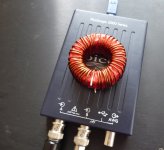
interesting project. My experience with similar inductors for this purpose (big toroidal ferrite core) was not very good - it saturated early. Of course it depends on core material and number of turns. My inductor is in the photo below.
Attachments
Most DSP settings are predictive 😛🙄if I typed ....'at the same time it would help others'
You would surely have asked......'how do you know?'
predicting this i tried to save myself the agony.
unfortunately you must be sharper than I thought and figured it out! 😀
No, just simple U-shaped loops.....the pads spacing (10mm or so ?) x 20/25mm or so high.
The twisting looks good provided the wire is looped back on itself before the twisting, the aim is to make 'non directional wire' links.
When you get enameled wire twisting the two links together before soldering to the board is preferable to separated links.
Dan.
10-4,
Yah I noticed it untwisted a little when I looped it.
What’s the best (reasonably priced) DMM.......there seems to be no lack of choices! I suppose my analog meter is probably 30yrs old it’s about time to upgrade. This one looks good?
2706B BK Precision 3.5 digit Handheld Multimeter New
Another suggestion - for low level signals inside the amplifier, use only shielded cables. Coaxial topology for single ended signals, with minimum shield impedance, shielded twist pairs for balanced signals. Never use unshielded cables - they will always catch HF EMI interference signals and pollute the audio signal. Even if the case is acting as a good shield, internal sources like transformer, diode rectifiers and filter capacitors will always create HF interferences. It is unavoidable.
Thanks Pavel,
I suppose that’s one of the benefits of RM’s driveway sealer dac, and Dans goop?!
On this subject that’s one of the things I want to try is getting a decent preamp and trying the HT bypass which basically turns the integrated to just a amp.
I’m not sure if the low level signal path will shorten enough to make a difference?
https://parasound.com/product-images/hint_black_inside.jpg
Ok, both the filter sections on the solar inverter pcb are CM filters, one section is solar panel DC input CM filter, with polarised electro cap across output of the filter section....this polarised cap could be removed or replaced with film cap for AC usage.Max, any idea what is inside those inductors in the AC and DC filters?
I already have this filter in series with the DC supply to my laptop and have found it to be an improvement.

My interest is more on this AC filter pcb which can be modified easily by cutting two pads and inserting an isolation transformer.


I intend cutting the pads connecting L2 and L3 and wiring in a screened torroidal isolation transformer.
This isolation/filtering section is to power the laptop only.
I will cull the AC section that is on the large pcb shown in my earlier post and use it to filter the second AC output of this power conditioning box with the second circuit powering the amp and sub only.

Questions to experts, should I put caps or RC networks across the iso transformer primary and secondaries, IOW across output side of L2 and input side of L3.
Currently fitted C1 - 0.22uF, C2 - 0.33uF, C3 - 3.3uF.
Dan.
Last edited:
Thanks Pavel,
I suppose that’s one of the benefits of RM’s driveway sealer dac, and Dans goop?!
Hi Bob,
I apologize but I do not know what is the principle of Dan's goop. My suggestion is based on continuous experience since the end of seventies of the 20th century till now. I know that John JC has different suggestions and uses bare wires inside the BT. Such is life. So you may try and decide.
I do not know if Halo Integrated uses any unshielded link/phono level cables. If it does, my suggestion is to replace them with the shielded ones.
When you get the enameled wire, lead free solder, liquid flux etc and iron I will give you more detail on what to do.10-4,
Yah I noticed it untwisted a little when I looped it.
You are checking volts and continuity, your existing meter is plenty good enough.What’s the best (reasonably priced) DMM.......there seems to be no lack of choices! I suppose my analog meter is probably 30yrs old it’s about time to upgrade. This one looks good?
2706B BK Precision 3.5 digit Handheld Multimeter New
I have had to use those el cheapo $10.00 DMM's and they actually work perfectly fine for checking ohms and volts.
There are good meters on Ebay pretty cheap, the BK looks good too.
Dan.
Put the list together and will order up some stuff today.......there’s a fly tying shop near me, I’m going to see if they have one of those old magnifier lights ‘in the back’
I know their a bit pricey but it looks as though I might benefit from a desoldering tool with built in suction?
I know their a bit pricey but it looks as though I might benefit from a desoldering tool with built in suction?
CDP with variable output or USB soundcard with variable output are ideal for use with that direct input.On this subject that’s one of the things I want to try is getting a decent preamp and trying the HT bypass which basically turns the integrated to just a amp.
I’m not sure if the low level signal path will shorten enough to make a difference?
https://parasound.com/product-images/hint_black_inside.jpg
First thing to do is to remove those ferrites and then to rewire the outputs and the problems you have with it will I venture reduce if not disappear. 😉.
Dan.
- Status
- Not open for further replies.
- Home
- Member Areas
- The Lounge
- John Curl's Blowtorch preamplifier part III