I had a neutral 'smoulder up' from a dryer once. In a wooden house. melted up about 4 inches before I found it and scared me witless.
As a side note, Home Depot employees are not allowed to give advice on what plug to use nor how to wire it. So either you come in knowing code, or you get a qualified electrician to do the work.
Yes, you get advice like it's OK to wire your range with #10 wire as long as you use a 50A breaker.
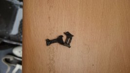
why I am not fond of dryers and distrust certain types of crimp connections in high current applications. That was the neutral connection from the heating element on my dryer. Or at least what was left of it.
Those connections now get a regular inspection.
Those connections now get a regular inspection.
Attachments
Standard practice in West Australia was to strip a section of the the insulation of the heavy cable, wrap the house circuits PE wires and the earthing rod wire around the bared section of the heavy cable, solder with gas torch and then wrap with green/yellow tape.
Dan.
Perfectly acceptable as long as you have a sufficient supply of marshmallows and green saplings to hold them over the fire. Until the firefighters get there of course.
Thanks Dan, for showing everybody a perfect example of what not to do. While you say it is "common practice" there, it is absolutely dangerous, and should be properly fixed. Multiple instances of a really dangerous thing does not make it correct, nor acceptable. Looks like you had a rash of one or two people doing multiple houses all badly.
Flame soldering is wrought with issues. The flame kills the flux it contacts, there is no control over the conductor temperature, you have no idea how hot the solder actually got (at elevated temperatures, solder will dissolve much more copper into solution so will compromise the cross section of the conductor). For copper pipe soldering, the flux is fully protected from the flame where it needs to clean, so activates the copper prior to the copper reaching solder melt temps, whereby the solder then wicks in by inter-metallic formation, and excludes the flux.
One caveat I see a lot of...many plumbers are in a hurry, time is valuable. So they many times use a really hot torch to solder fittings. The problem is, it is possible to overheat the flux immediately under the flame before the edge of the fitting is hot enough to melt the solder (very high heat flux can cause a horizontal heat gradient within the fittings. So they are by design, generating a large area of the joint where the flux fails to protect the just cleaned copper surface. It is far better to use less heat so that the entire joint is at the same temperature, problem is it takes time and is very dependent on pipe size, gauge, fitting mass, and fitting allowed temp.
A stranded conductor will not really protect the flux from the flame, so it heavily compromises the entire solder joint.
Also, these joints are really not protected by tape wrapping, so the environment will setup electrolysis to compromise the joints as well.
It is precisely this type of anarchy that led to the creation of the NEC.
edit: almost forgot. When a stranded wire is soldered, there is an interface between where the solder is, and where it isn't. When the resultant wire is bent, the wire will tend to bend where the solder has stopped, as the solder filled portion will have a high resistance to physical bending. Many times, that is exactly where the wire will fatigue and fail if subject to more than one or two bends.
jn
Last edited:
Oh, come on, you don't want to insult someone who is at pro level. 😀Like you are?
Like you are?
No, he's a goocomedian. Wait, make that a gooprofessional.
JN,
Time to use a current probe! The motor should be at most a few amps. As 10 gauge is rated for 30 amps and most consumer dryers are below that, I would really want to know why there is any discoloration.
Personally I try to always over size the wire, so my 20 amp breakers are wired with 10 gauge.
I did get into the NEC a note that is is okay to oversize the conductors particularly in applications such as the compressors used in ice arenas. The electricians at one site kept insisting over-sizing wasn't following code. The cost savings from the reduced losses save more than $1,000 per month. Payback was a few months. Had the same problem later at that place when I wanted 10 gauge for my audio rack circuits even though they were 20 amp circuits. Later they didn't want to change the transformer taps to raise the mains voltage. It dropped to 108 under load! Claimed it would damage the computer power supplies. They did burn out just about every lights' electronic ballasts with low line voltage!
Now we could chat about what the rated gauge really does to the older analog power supplies in audio power amplifiers and their ability to meet peak power levels!
Last edited:
I have never seen a soldered joint in any home installation but...
Current version of (110.14B) Conductor Splices. Conductors must be spliced by a splicing device identified for the purpose or by exothermic welding.
...insertion of any device with reactance within the bonding run is absolutely forbidden. If in the future NEC allows UL listed devices within the bonding path, that would be great. Until then, I can not recommend using anything in that path, no matter how good anybody thinks it sounds..jn
Indeed, you do not want to run ground bonding conductors in steel conduit if the conduit is not also bonded at both ends for the same reason: it can increase the inductance of the internal grounding run. and it's impedance will rise with frequency...just what you do not want during a lightning event with significant RF energy. This will encourage potential rise on the inductively isolated segment of the system. If the conduit is also bonded per 250.102(C) it is then in parallel to the ground path, lowering impedance.
Cheers,
Howie
edit: almost forgot. When a stranded wire is soldered, there is an interface between where the solder is, and where it isn't. When the resultant wire is bent, the wire will tend to bend where the solder has stopped, as the solder filled portion will have a high resistance to physical bending. Many times, that is exactly where the wire will fatigue and fail if subject to more than one or two bends.
That is why in all aviation and automotive standards, wire soldering is not allowed for wire splicing or wire to connector pin joints when outside of enclosed electronic units. Where vibration exists, soldered wire cracks at the end of the solder.
George
dan,
It is not illegal to have an inductor in the safety ground.... but must be done without splices and soldering or brazing etc. So, I assume you could thread a ground wire around a core and then terminate it on the grndneut. block. OR, maybe get your inductance by adding a clamp on -- ferrite -- ?
In the Monster -7000 I had all three wires run thru and looped around a ferrite CM core before going to the chassis grnd and other circuitry.
-RNM
Last edited:
As I was prepping the new 4 wire outlet, I reviewed the three wire one. At first, I was confused...(yah, ok I know I'm setting myself up here).
The old 3 wire was a 10-2 conductor, the bare copper was used for neutral, white and black were both hots. So, the wire I was mis-posting as neutral was in fact a hot leg.
The reason it burned was that the terminal was not tight enough, that much is clear.
Despite that error, the discussion of keeping neutral and safety bond separate is still totally valid.
RM..
Be careful in saying an "inductor is perfectly legal" in a safety ground. Your wiring caveats are totally great and agreed upon. The issue is the level of voltage that the reactance will drop when ground currents are flowing. How fast the overcorrect device trips is totally dependent on how much current the fault will generate. If the current is insufficient, the bonded device will remain at a voltage over 50...not good.
In the case of Dan, he is speaking of an inductance that will be inserted such that surges have to go through it to earth, as well as a reactance to limit AC fault currents. Certainly not an engineered solution.
jn
In old Knob and Tube home wiring systems, soldering was the standard way of making spliced connections.I have never seen a soldered joint in any home installation but...
Knob and Tube used individual Black & White wires spaced a few inches apart. With ceramic tubes to go thru building framing and ceramic knobs for support at turning points and junctions. There was no Safety Ground wire. A big problem was that electricians were not careful about keeping the Black & White in a one-to-one relationship and often connected to any nearby White wire.
You referenced article 110.I have never seen a soldered joint in any home installation but...
Bonding and grounding is article 250. I do't have access to my NEC to look it up, but I just went through this at work, and emailed some fellow workers the exact 250 reference that says no soldering allowed on bonding conductors. I'll have access on Thursday to the information.
jn
...It is not illegal to have an inductor in the safety ground...-RNM
Richard,
We need to differentiate between structure wiring and internal equipment wiring.
With regards to grounding of all structural devices, there are two requirements: adequately low impedance and current-carrying capacity at 60 Hz to ensure proper operation of over current devices, and equalization of surge potentials from the device to the grounding electrode over a broad range of frequencies as rapidly as possible and with as little voltage drop as possible.
With regards to plugged-in devices, the 60 Hz low impedance and adequate current-carrying capacity mandate applies, but there is no strict HF impedance requirement, although for a device such as a power conditioner, the ability to shunt a broad frequency range of energy from devices plugged in (Cable, TV antenna, Satellite dish receiver) directly to the grounding conductor is beneficial.
Cheers!
Howie
Last edited:
I had a query regarding the ground wire running through pipe. In order to not have the pipe raise the inductance of the ground conductor you are required by code to use a conduit grounding connector or other approved conduit bonding device when passing grounding conductors through steel or iron pipe:
https://www.ecmag.com/sites/default/files/styles/article_medium/public/xml_uploads/unzipped/grounding_bar_iStock_000013797691Small_0.jpg?itok=0_RJUnOk
Yes Virginia, there is such a thing as electrician porn.
Howie
https://www.ecmag.com/sites/default/files/styles/article_medium/public/xml_uploads/unzipped/grounding_bar_iStock_000013797691Small_0.jpg?itok=0_RJUnOk
Yes Virginia, there is such a thing as electrician porn.
Howie
In old Knob and Tube home wiring systems, soldering was the standard way of making spliced connections.
I said I never saw one. Here it is not grandfathered in, in general you can neither finance or insure a house with it.
Massachusets has lots of rules and laws (so does Chicago) that other parts of the country don't. Many old cities delete parts of the NEC code because of the high expense of those rules would mean that people won't do any rework on their old homes.I said I never saw one. Here it is not grandfathered in, in general you can neither finance or insure a house with it.
All of the lighting circuits in my 1938 house (newest home in the neighborhood) are still Knob & Tube.
All of the lighting circuits in my 1938 house (newest home in the neighborhood) are still Knob & Tube.
1938 is a little late in the game, my first house (1924) and my grandfather's house (1923) were armored BX which is allowed to remain in most places. I appreciate the financial issue and I realize some places allow K&T for ceiling lights and wall sconces, etc that are hard to replace.
I wouldn't expose my family or guests to any bathroom or kitchen outlets tied to it for any money saved.
- Status
- Not open for further replies.
- Home
- Member Areas
- The Lounge
- John Curl's Blowtorch preamplifier part III