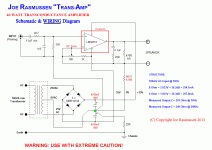
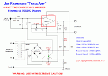
Doesnt matter if there are some wrong parts. fix them for him/her. However, it does work in practice. Find a better explaination then but cant deny it does reduce distortion. That is what is important. it will work on most any amp or speaker.Yes you read the stuff (including the obviously wrong part) and make no comment, amazing actually stunning.
isnt that a good thing? should be incorporated into all amp designs used to drive speakers. Improved sound for the price of one resistor? Come on. why fight it? use it.
How about exploring it more. I figured something out and it works. maybe you can be the one to do a technical treatise on it complete with math formulas and all.
-RNM
from JR --

Last edited:
Find a better explaination then but cant deny it does reduce distortion. That is what is important. it will work on most any amp or speaker.
You don't get it he is not doing any of this stuff, and even denies it strongly. There is no sense resistor or feedback involved an ordinary amplifier connected directly to the speaker.
I suggest you take a peek at The Audio Critic #16 (1991, easily found on-line), which contains Part II of their wire and cable series. It presents some nice graphs of "computer simulated" FR tests based on measured amplifier Zo for two different amplifiers, measured Z vs F for some loudspeaker, and measure L/C/R for several types of speaker cable. The simulations assumed 10m of the cable. Quite enlightening, and indicative of what EE's actually do. Measure, measure, measure, then see what happens.When we went from tube PAmps to SS, we noticed, by listening, that the bass was deeper, tighter, more accurate. Same effect occured when we used very thin speaker wires compared to thick (large AWG). Larger affected the bass ... deeper,louder etal.
So what do EE do? They measure the damn wire by itself and proclaim nothing there... small Rs. Cannot have any affect on the sound.
...
THx-RNMarsh
Aw shucks, Joe, you don't have to get all emotional just because so many people here have corrected you."Correct a ridiculer and he will hate you for it, correct a wise man and he will love you." Solomon
Still talking at cross purposes Richard, why is that? Motional feedback? Where does that fit in exactly?
You might like this as well https://www.eetimes.com/document.asp?doc_id=1274851#I suggest you take a peek at The Audio Critic #16 (1991, easily found on-line), which contains Part II of their wire and cable series. It presents some nice graphs of "computer simulated" FR tests based on measured amplifier Zo for two different amplifiers, measured Z vs F for some loudspeaker, and measure L/C/R for several types of speaker cable. The simulations assumed 10m of the cable. Quite enlightening, and indicative of what EE's actually do. Measure, measure, measure, then see what happens.
-RNM
see above #25568 See the 0.R33 resistor?You don't get it he is not doing any of this stuff, and even denies it strongly. There is no sense resistor or feedback involved an ordinary amplifier connected directly to the speaker.
-RNM
I called it motional (not cone movement) but I would say back-emf and is more accurate. Same circuit I am talking about.Still talking at cross purposes Richard, why is that? Motional feedback? Where does that fit in exactly?
This topology---->

-RNM
see above #25568 See the 0.R33 resistor?
That has nothing to do with his Elsinore speaker which is what we are discussing "a current or voltage friendly speaker". Why aren't you using it BTW, I don't see any of this on Damir's amps.
Last edited:
That has nothing to do with his Elsinore speaker which is what we are discussing "a current or voltage friendly speaker".
When he talks about back-emf (of any speaker system... his or others does not matter)..... then the resonance of the speaker will be the primary generator of the back-emf.
Using the back-emf can lower distortion at the resonance region in a way box loading cannot..... sampling the current.
A lot of what he was talking about relates also to his amplifier as shown. Maybe he just has not got there yet, here. But he certainly is using my idea. So, I am just jumping ahead.
EE's job here is to explain the reason for the distortion reduction from the driver.
THx-RNMarsh
Last edited:
jn is the person for this, he knows more about it than most. BTW the shunt networks on the speaker defeat the current sensing of the actual driver's current so you don't want both the current drive and impedance correction.EE's job here is to explain the reason for the distortion reduction from the driver.
Series resistance leads to more "current-like" drive, thus distortion may be reduced, depending on speaker. At the same time, frequency response will be more uneven, less flat. Electro-dynamic speaker needs voltage drive for the most flat frequency response. But, current drive is best for lowest distortion. If you want both, you have to use a current drive with DSP frequency response equalization (inversion of impedance curve). This is known, proven and discussed even in this thread. Active crossover (impossible to use passive crossover with a current drive), every speaker driven by its current source and DSP equalization of every speaker used.
Active crossover (impossible to use passive crossover with a current drive), every speaker driven by its current source and DSP equalization of every speaker used.
That would be very interesting to hear. Unfortunately, it would have to be cobbled together to try it, at least I am not aware of an existing system designed to work that way.
That would be very interesting to hear. Unfortunately, it would have to be cobbled together to try it, at least I am not aware of an existing system designed to work that way.
There is a guy here who has designed and built it. With in-wall speakers. Unfortunately, I have not heard it, yet.
The distortion probably drops at resonance because the power required for the same acoustical output drops dramatically - in a severe case maybe by 6-8 dB ( power). If you are using current feedback, the effect will be even more dramatic.
One of the most natural sounding speakers I have ever heard are the Graham Audio LS5/9f floor standers. Simple cross over, bass/mid driver and a soft dome tweeter. Fantastic for jazz and classical.
One of the most natural sounding speakers I have ever heard are the Graham Audio LS5/9f floor standers. Simple cross over, bass/mid driver and a soft dome tweeter. Fantastic for jazz and classical.
So is it that you don't know what a reed relay is, or that the reed must be magnetic, or what material the reed is made of, perhaps you just don't know what hysteresis means?Right, I see you are still building your own private physics.
A well known and measured issue with reed relays. Also hysteresis issues pop up when wiring inside a steel chassis.
It may look that way on paper (or CAD) but in practice, i did not see that occure with this fb topology. As I reported in the article, the bass was extended slightly as well No peaking noticed. A JBL D130 (15 inch ) in large enclosure volume. Measured both in rear loaded horn and in bass-reflex.Series resistance leads to more "current-like" drive, thus distortion may be reduced, depending on speaker. At the same time, frequency response will be more uneven, less flat. Electro-dynamic speaker needs voltage drive for the most flat frequency response. But, current drive is best for lowest distortion. If you want both, you have to use a current drive with DSP frequency response equalization (inversion of impedance curve). This is known, proven and discussed even in this thread. Active crossover (impossible to use passive crossover with a current drive), every speaker driven by its current source and DSP equalization of every speaker used.
THx-RNMarsh
Last edited:
Not the pictures I was referring to, it was simple I/V characteristics presented 0 conductivity at the origin and sudden break point at some voltage. This characteristic will rectify if it is stationary.
Just like a coherer except you have to reset after each pulse. Once breakover occurs the resistance drops and stays low. All this occurs at 50 to 100 millivolts not the 270 volts for a gas insulator.
As I said never observed it, is that OK? I wish I had the picture I don't remember the I/V after the singularity pointing back through the origin as it would if the resistance dropped to a low value.
Last edited:
So is it that you don't know what a reed relay is, or that the reed must be magnetic, or what material the reed is made of, perhaps you just don't know what hysteresis means?
A well known and measured issue with reed relays. Also hysteresis issues pop up when wiring inside a steel chassis.
I do, and magnetic components is one of the most perpetrated BS in audio. Steel chassis magnetic effects are real, for power amplifiers @high currents and ppm level distortions. No permanent magnets involved.
We need to put numbers on these things since some extraordinary resolution is now available. I was able to detect -145dB 3rds in a 1 kHz 600 Ohm L/C filter @7V rms siting on a steel lab bench.
The LA article gave -150dB up to 2Vrms into 2K or so for reed relays. AFAIK all our A/D and DAC demo cards were made with off the shelf SMT parts to take all the datasheet curves.
The LA article gave -150dB up to 2Vrms into 2K or so for reed relays. AFAIK all our A/D and DAC demo cards were made with off the shelf SMT parts to take all the datasheet curves.
I do, and magnetic components is one of the most perpetrated BS in audio. Steel chassis magnetic effects are real, for power amplifiers @high currents and ppm level distortions. No permanent magnets involved.
I'll take that to mean you don't know what a reed relay is! There is nothing in this about permanent magnets.
The issue is clear there is distortion when a wire carrying current is placed next to or through a steel or iron based material. The issue is at what level does this occur. If it were a larger issue far more folks would not use them. At the normal low levels it is not an issue for the folks who use them. When it is a problem there are other relay choices.
That is why being informed is the first step. No violation of the commonly accepted laws of physics.
We need to put numbers on these things since some extraordinary resolution is now available. I was able to detect -145dB 3rds in a 1 kHz 600 Ohm L/C filter @7V rms siting on a steel lab bench.
The LA article gave -150dB up to 2Vrms into 2K or so for reed relays. AFAIK all our A/D and DAC demo cards were made with off the shelf SMT parts to take all the datasheet curves.
And since -150 dB is good for 24 bits of resolution they should be fine for the application. I have some old ones removed from an amateur built mixing console. Ones intended to be a power relay as far as reed relays go. Source impedance 100 ohms, load 10,000 ohms and distortion -122 dB re 1 volt. Not a good choice as less expensive and better audio relays exist.
BTY those miniature Teledynes relays really are great and of course pricey.
- Status
- Not open for further replies.
- Home
- Member Areas
- The Lounge
- John Curl's Blowtorch preamplifier part III