Hi Keantoken,
If you couple the metallic path with a transformer, then yes. The optical fibre is isolated on it's own. Most SPDIF circuits are transformer coupled anyway.
-Chris
If you couple the metallic path with a transformer, then yes. The optical fibre is isolated on it's own. Most SPDIF circuits are transformer coupled anyway.
-Chris
Is there a definite answer to be found?
What I'm trying to figure out is, do the power wires at the input of the cable connect to the power contacts at the other end? If so, then it is not galvanically isolated.
Can you use a DMM to measure resistance between the ends of the cable on power pins and ground? There should be no conductive path between the ends of the cable, for it to be useful for ground loop mitigation.
be over here in Asia (Bangkok) for the next 4 months.
Lucky man! Have said to myself for the past couple of winters I need to leave this gloomy h* hole up in the north and visit Th... maybe got to get that bang **** experience the coming winter. 😎
Hi Keantoken,
They will have continuity. It comes down to the circuitry at each end. There are switching regulators that isolate the power output side.
So to answer your question when it comes down to the conductive part of the cable, it is not isolated. If it is, then it is broken.
They will have continuity. It comes down to the circuitry at each end. There are switching regulators that isolate the power output side.
So to answer your question when it comes down to the conductive part of the cable, it is not isolated. If it is, then it is broken.
The Host powers the electro-optics on both ends, the signal is isolated. And it DOES use VCELS so it is easily good to 4 GHz.
When we designed our 10 GBps XFP/SFP modules at Infineon fiber optics
> 12 years ago we used VCXLs whenever possible. It was SOO much easier,
simpler, cheaper than DFB. Much less RF & DC current, cheap bias tees
or completely on the driver chip. But there were no VCXLs for 1550 nm.
Nobody could grow cavities that large.
cheers, Gerhard

Hi Ultima Thule,
You're making me work, and I would rather enjoy the posting. Please don't circumvent the nanny software again.
-Chris

cheap bias tees
We used BF862's with a source resistor, a couple of SMT caps, and a piece of wire for a demo. I designed a phantom powered receiver but the project died before we packaged some. IIRC they self destructed at only 3-5mA DC current. We used Ulm BTW, are they near you?
Aye aye, sir!
edit: we ought to age restrict the lounge, kids do not trespass!
edit: we ought to age restrict the lounge, kids do not trespass!

Attachments
Last edited:
We used BF862's with a source resistor, a couple of SMT caps, and a piece of wire for a demo. I designed a phantom powered receiver but the project died before we packaged some. IIRC they self destructed at only 3-5mA DC current. We used Ulm BTW, are they near you?
The city of Ulm is abt. 1h by car from where I use to work.
Yes, laser diodes are picky when it comes to their operating point.
10% less current and the extinction ratio is gone and the eye is closed,
a little bit too much and the cavity mirrors evaporate.
But they still keep working as an infrared LED 🙂
BTW I took this chopper amplifier out of the drawer on this rainy week end.
Soo large switching transients! :-(
cheers, Gerhard
Gerhard, Remember for most uses the fiber lengths are fairly long, with short lengths, 1-3 m and if using terminated fibers, you have back-reflection problems unless you go for expensive termination and fiber polishing schemes and use sources like DFB. VCSEL's are not immune to back-reflection problems. In the Corning device, a silicon waveguide is used circumventing the back-reflection problems at the wave-guide fiber interface.
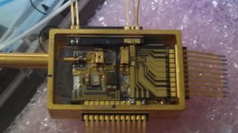
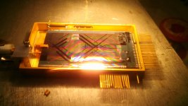
Now how do the get the VCSEL into the waveguide? Do they use a well and mount it on its side, Do they P-Down mount into an angled reflector? Are they using a newer hybrid VCSEL? The most elegant was I know of had been patented by a small company. They bring the waveguide to the surface of the silicon substrate and evanescent field couple via tightly controled
P-Down bonding.
We used TO-52 TOSAs, and these were swimming in the XFP module,
connected to the transceiver board itself with flexible Kapton bands.
The production could be made automatically, but getting the flexible
link OK at 10 GBPS required an enormous amount of 3D electromagnetics.
The TOSAs had a quartz window with optical 3 dB attenuation or so.
That ensured enough optical s22 🙂
It looked this way:
< http://www.hoffmann-hochfrequenz.de/project_gallery/10GBit_XFP_q58.jpg >
WRT the Corning cables, not that I'm holding out, but I don't like to make assumptions about what's in the device.
That said, what if one cut the power wires in it and powered the other end with another power source? Sounds like it could be easily modified.
That said, what if one cut the power wires in it and powered the other end with another power source? Sounds like it could be easily modified.
The power is basically to enable the transaction from light to electricity. There is a laser diver and I/V converter for the photodiode. The DB lines in the Corning USB cannot power peripherals. The Signal lines are not only isolated, they also can't act as antennae.
I don't see why you could not used a separate PS since the optronics are isolated
I don't see why you could not used a separate PS since the optronics are isolated
Back to audio. I spent a couple of days at the Rocky Mountain Audio Fest in Denver and I heard some good sound, and saw lots of enthusiasm for exotic audio projects like analog recording and extreme attention to vinyl reproduction. CD reproduction was almost nonexistent, compared to vinyl, analog tape and digital streaming for some reason, perhaps a combination of highest quality source need and convenience (streaming)
I heard some very refined audio systems there and I can assure you that ultra quality is not dead, but perhaps more condensed into people who are willing to invest into it. The very best is not cheap!
Many people in DIY don't really count the number of hours that they invest into their projects as a fixed price per hour, but hi end projects are very much like DIY in that they cannot be easily mass produced and the hours add up. The only other factor is that some hi end companies will invest in the VERY BEST materials rather than something more commonly available, because the best materials usually perform better, and they 'look' better as well. Both factors are important to satisfy the hi end customer who usually has the 'best' in his home environment.
I tell you what: Just take your DIY design, and count the hours designing and building it and add perhaps $50/hr for your total hours. THEN you will know the price of your project.
I have noticed a resurgence in old reel to reel tape decks. There is a fad element to tape decks and vinyl. The younger folks are buying them up and at the same time discovering better sound. Most of the younger acts produced music in CD, Steam or download and vinyl these days. But these aren't geared to the High End as these kids can't afford it because of high rents, large student debt, all kids of stuff us oder type never had to deal with
What I saw at RMAF was NOT fad or cost effective, when it came to either analog tape recording or vinyl playback. In fact, just because I paid $100 for a vinyl test pressing of one of my favorites, there is NO WAY I can afford $450-$500 for a 15ips 1/2 track analog tape. Yet there is a growing interest in the 'best', something many of you have never really heard.
Met 7's? I own 3 pairs of them, but they do not compare to my reference loudspeakers, but are 'easy listeners' that are good for TV and other typically digital sources. Quality vinyl? They are too forgiving. Chip based power amps? I don't think so.
Met 7's? I own 3 pairs of them, but they do not compare to my reference loudspeakers, but are 'easy listeners' that are good for TV and other typically digital sources. Quality vinyl? They are too forgiving. Chip based power amps? I don't think so.
- Status
- Not open for further replies.
- Home
- Member Areas
- The Lounge
- John Curl's Blowtorch preamplifier part II


