Thanks, good link. Found a lot on Google but not this one which addresses exactly my query.
So, if I want to judge stability (gain/phase margin) I should use the noise gain version of the loop gain.
For the inverting config loop gain is -β*Ao; for the non-inverting version it is (β+1)*Ao. Right?
Jan
For my understanding loop gain is the same in both configurations, because this does not depend of the non.inverting input being grounded directly or through a voltage source with zero impedance.
Signal gain differs.
That was my initial thought, because loop gain depends on the attenuation of the output to the input and the open loop gain. And those are the same in both cases; the lower signal gain in inverting mode is really due to forward attenuation of the input through the feedback network.
But then I got to doubting my reasoning because then I thought, noise gain is what drives stability, noise gain is different in the two situations and I thought therefor loop gain must be different. Hmmm.
For instance, when we do a loop gain measurement by breaking the loop, inserting a signal and measuring the output at the other side of the break, we do in fact measure loop gain. And we use that to determine stability, but stability is really determined by the noise gain times Ao (or 1/NG*Ao). I think.
Am I confused?
Jan
Last edited:
For a forward gain of one, an inverting amplifier will have 6 dB more noise gain. Which means, yes, you do consume more loop gain in the inverted configuration.
So perhaps easier to write the total available gain is conserved, but yes there's is less loop gain in an inverted amplifier due to that 1+ term.
So perhaps easier to write the total available gain is conserved, but yes there's is less loop gain in an inverted amplifier due to that 1+ term.
Jan, You might want to take a look at this application note: https://linearaudio.nl/sites/linearaudio.net/files/Graeme feedback models reduce opamp circuits.pdf that someone has marked up to correct typos, etc.
It talks about a case where there is both positive and negative feedback, as can be found in some op-amp circuits.
Also perhaps helpful to remember, the equation for closed loop gain can be easily derived by solving the loop equations for simple amplifier circuit. Going through the exercise might help improve intuition of how block diagrams relate to circuits.
Also, the concept of noise gain (from Black?) has to do with the idea that when we measure noise, we might short the input and measure at the output. By doing that we could model all the noise sources in the circuit as one lumped generator at the output. However, it may be more convenient for some purposes to model the lumped noise generator as being located at the inverting input of the op-amp. The noise gain is the factor that relates the lumped model generator at the inverting input to the corresponding generator we could put at the output instead. Again, solving loop equations should give the right answer in every case.
I hope I haven't confused things too much more by trying to explain things this way. Hopefully some of it will help you feel more comfortable with the models.
Last edited:
Well, my assumption is based on no parts changing.
Obviously, neither loop gain nor noise gain are affected when inserting a zero impedance source either at non.invdirectly or at the cold end of inv input input resistor, respectively.
But the signal gain obviously is +1 higher driving the non.inv input.
Obviously, neither loop gain nor noise gain are affected when inserting a zero impedance source either at non.invdirectly or at the cold end of inv input input resistor, respectively.
But the signal gain obviously is +1 higher driving the non.inv input.
For a forward gain of one, an inverting amplifier will have 6 dB more noise gain. Which means, yes, you do consume more loop gain in the inverted configuration.
So perhaps easier to write the total available gain is conserved, but yes there's is less loop gain in an inverted amplifier due to that 1+ term.
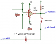
OK, I get that conservation of gain; it's just partitioned differently. But assume I want to measure loop gain in an inverting and a non-inverting case. The usual way is to short all independent sources, break the loop and measure the return. I get a circuit like the attached for both cases! So obviously my measurement will give me the same return for both cases because the test circuit is identical. Where did the difference in loop gain go?
I am not trying to trick anyone; I am genuinely puzzled about this!
Jan
Attachments
One of the later reviews of the V15 also touted its tracking ability. Shure used to have a technical paper on the subject. Some magazines used to test for tractability and report the results vs pressure setting.
Shure V15 Phono Cartridge Reviewed
...The V15 could take just about anything thrown at it. It also had fairly flat freq response and very good (for LP) channel separation vs freq.
RIP.
THx-RNMarsh
In my experience the last version of the venerable V15 which was designated the V15VxMR is a truly excellent cartridge overall, certainly the best MM I have heard, and the equal of many MC carts. I moved from an Ortofon MC2000 (a pain to setup) to the V15VxMR and did not look back, say what you will about my preferences in vinyl reproduction...but the additional low-level detail and lack of tracing distortion was a major improvement.
Fortunately JICO in Japan is making superior replacement styli for them, with pretty stunning results. They are offering both sapphire and ruby cantilevers with Super-SAS tip profiles. I am using the sapphire version and it is noticeably cleaner sounding than the original Shure Micro-Ridge, likely due to a combination of tracing area and lack of resonance in the audio band. The availability of these styli make the used V15s on eBay look like viable purchases...
Just my $0.02 worth
Cheers!
Howie
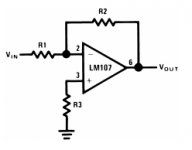
Jan, I will post two images of an inverting amplifier below. The first one is closed loop, and the second one is with the loop broken. If we take the broken one and ground the point marked Vin, and add an input signal directly into the point marked pin 2, you can see that the two resistors connected to the output and ground form a voltage divider than returns less than the full amplifier output to the point where the cut was made (that used to be connected to pin 2). If it was a unity gain circuit with R1 = R2, then the return voltage would be half the output.
Does that much make sense so far, would you say?
Does that much make sense so far, would you say?
Attachments

Last edited:
OK, I get that conservation of gain; it's just partitioned differently. But assume I want to measure loop gain in an inverting and a non-inverting case. The usual way is to short all independent sources, break the loop and measure the return. I get a circuit like the attached for both cases! So obviously my measurement will give me the same return for both cases because the test circuit is identical. Where did the difference in loop gain go?
I am not trying to trick anyone; I am genuinely puzzled about this!
Jan
Jan -- I don't assume you're playing games, so no worries. I'll need to look at something like how the Tian or Middlebrook probes work.
Also remember that if you're feeding the amplifier from the inverting pin, you'd be shorting pin 2 to ground. What you have shown is the non-inverting configuration only.
The images are the same...
Look at pin 2 of the opamp in Mark's images.
Anyway, I have to leave soon so to go on: It looks like in both our examples the loop gain = 1/2 x Ao. With the 1/2 being due to the voltage divider.
If we try the equivalent thing with a non-inverting buffer, there need not be any resistors and so there will not be a voltage divider. In that case it will turn out the loop gain = Ao.
If we try the equivalent thing with a non-inverting buffer, there need not be any resistors and so there will not be a voltage divider. In that case it will turn out the loop gain = Ao.
Wrong place to start man, should have been 432Hz 😎
No idea if it works (to induce relaxation). But it is worth a try. One could use a custom crystal (or a standard frequency that is close enough) to reproduce CDs or stream USB in asynchronous mode with 432Hz tuning. Or tweak the turntable speed. (Or do it in DSP. I would prefer the crystal method.)
432/440=0,98181818
44100*0,98181818=43298,18 Hz
43298,18*128=5542167 Hz (for a custom 128fs crystal)
5529600 is a standard crystal. You would be 1 Hz flat of 432 Hz.
Being squarely in your target demographic, let me provide my two cents best guess as to why hifi is dying amongst the newer generation...
It's EXTREMELY RARE a cell phone is farther than 8 feet at any time from someone in their 20's, 30's or even 40s. If it is, their tablet is nearby and they can use handoff to pick up the call on their tablet...
I apologize for my posts being so late, I have been kinda busy, but this one struck a chord with me: I am working with a team designing a new recording studio and they have issues suspected to be caused by a nearby cell phone tower inducing odd interference (>.8V/M broadband between 700 MHz and 3 GHz). I attempted to get them to look at the equipment they were using and the method of interconnection, but that was not on the table for discussion, the gear has to be flavor of the month. So I was asked to design RFI proofing for the studio, and I suggested using carbon-loaded RFI paint which offers very broadband and moderate RFI reduction (30-36 dB, 10MHz-6GHz). At first they were behind the plan, but then one of them asked if cellphones would still work, and when told it would reduce the cell signal levels, stated there is no way they could do it, because no band would want to work in a studio where they couldn't check texts every minute or so.
Having spent a large portion of my life in studios working on a customer's project or debugging noises and/or distortions, I can't even imagine the frame of mind where one could summon the necessary mental and aural concentration to properly mix, yet be worried about a text. Maybe I'm just stupid.
Anyway, this is from people who don't notice when they lean their cellphones against the equipment racks they hear odd noises...those microwave generators should be banned from studios. Of course if all pro audio equipment was designed like many used to be to operate correctly in high RF fields in a radio station it wouldn't matter. Downward pricing pressure from cheap imports has eliminated a lot of rf-proofing...
Howie
Different from tuning the instruments to 432Hz though (reproducing CDs at 43200 samples/s makes everything a bit slower, obviously).
Last edited:
In my experience the last version of the venerable V15 which was designated the V15VxMR is a truly excellent cartridge overall, certainly the best MM I have heard, and the equal of many MC carts. I moved from an Ortofon MC2000 (a pain to setup) to the V15VxMR and did not look back, say what you will about my preferences in vinyl reproduction...but the additional low-level detail and lack of tracing distortion was a major improvement.
Fortunately JICO in Japan is making superior replacement styli for them, with pretty stunning results. They are offering both sapphire and ruby cantilevers with Super-SAS tip profiles. I am using the sapphire version and it is noticeably cleaner sounding than the original Shure Micro-Ridge, likely due to a combination of tracing area and lack of resonance in the audio band. The availability of these styli make the used V15s on eBay look like viable purchases...
Just my $0.02 worth
Cheers!
Howie
I saw measured results of JICO stylus in V15 and it had very sharp HF peak
at 13Khz , which was results of high effective mass compared to original which had very low eff. mass of 0.19mg and resonant freq. at 35khz. It gave a bright subjective sound quality, which some think is improvement. Shure Micro -Ridge is the most advanced stylus shape.Thin wall berylium cantilever is the lightest ever produced.
In my experience the last version of the venerable V15 which was designated the V15VxMR is a truly excellent cartridge overall, certainly the best MM I have heard, and the equal of many MC carts. I moved from an Ortofon MC2000 (a pain to setup) to the V15VxMR and did not look back, say what you will about my preferences in vinyl reproduction...but the additional low-level detail and lack of tracing distortion was a major improvement.
Fortunately JICO in Japan is making superior replacement styli for them, with pretty stunning results. They are offering both sapphire and ruby cantilevers with Super-SAS tip profiles. I am using the sapphire version and it is noticeably cleaner sounding than the original Shure Micro-Ridge, likely due to a combination of tracing area and lack of resonance in the audio band. The availability of these styli make the used V15s on eBay look like viable purchases...
Just my $0.02 worth
Cheers!
Howie
Thank you for the update. It is truly good news for LP users today. If I had an LP system, this is what I would explore this myself.
THx- Richard
Last edited:
Tubes are inherently more linear than semiconductors all by themselves. I would love to hear your amp, Wavebourn, and perhaps I will at the BA meeting.
Hope you can make it, John. That would be great 🙂
The time has come to learn design rf-immune audio 😉I apologize for my posts being so late, I have been kinda busy, but this one struck a chord with me: I am working with a team designing a new recording studio and they have issues suspected to be caused by a nearby cell phone tower inducing odd interference (>.8V/M broadband between 700 MHz and 3 GHz). I attempted to get them to look at the equipment they were using and the method of interconnection, but that was not on the table for discussion, the gear has to be flavor of the month. So I was asked to design RFI proofing for the studio, and I suggested using carbon-loaded RFI paint which offers very broadband and moderate RFI reduction (30-36 dB, 10MHz-6GHz). At first they were behind the plan, but then one of them asked if cellphones would still work, and when told it would reduce the cell signal levels, stated there is no way they could do it, because no band would want to work in a studio where they couldn't check texts every minute or so.
Having spent a large portion of my life in studios working on a customer's project or debugging noises and/or distortions, I can't even imagine the frame of mind where one could summon the necessary mental and aural concentration to properly mix, yet be worried about a text. Maybe I'm just stupid.
Anyway, this is from people who don't notice when they lean their cellphones against the equipment racks they hear odd noises...those microwave generators should be banned from studios. Of course if all pro audio equipment was designed like many used to be to operate correctly in high RF fields in a radio station it wouldn't matter. Downward pricing pressure from cheap imports has eliminated a lot of rf-proofing...
Howie
(cough) this will ban tubes, will it?
Last edited:
The time has come to learn design rf-immune audio 😉
(cough) this will ban tubes, will it?
...and transformer balanced inputs. ;-)
- Status
- Not open for further replies.
- Home
- Member Areas
- The Lounge
- John Curl's Blowtorch preamplifier part II