with photonics, good yield is about 60%. High power lasers about 25 to 40% is standard. Depending on the growth, etching etc, a lot of interactions at the edge of the wafer. Lasers closest to center are always best. Grow is controlled to the angstrom with MOCVD
using same mfr process, the results can be quite consistent when using jFETs from same date code. Does this indicate the setup and/or materials per mfr run is variable in some way ?
JFET Variation
THx-RNMarsh
JFET Variation
THx-RNMarsh
Last edited:
The diffusion depth/material isnt controlled well enough?
-RNM
It's probably much harder. With JFETs, you usually have a gate connection on the top
AND on the bottom of the chip; that's why IF3601, U310 have the gate connected to
the case. It comes naturally if you solder the bottom metallization to the carrier.
Or why SOT-23-Fets have the gate on the center pin.
That brings the mechanical thickness of the die into the equation for channel depth.
With planar BJTs, the whole structure is just a few 1000 atoms thick.
Last edited:
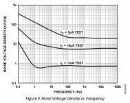
I was looking at the relatively new LT6018 this evening, and wonder what is the secret behind the very low LF noise.
Also seems that no one is using it for audio, yet......
http://cds.linear.com/docs/en/datasheet/6018f.pdf
I just looked at the MAT12 / SSM2212 which seems to be the same chip.
Where does that funny notch at the 1/f corner come from?
Is that physics or just curve fitting gone hiwire?
Attachments
I just looked at the MAT12 / SSM2212 which seems to be the same chip.
Where does that funny notch at the 1/f corner come from?
Is that physics or just curve fitting gone hiwire?
Those would be chart tape rolling or when an old layout was reshot the tape had lifted and someone who knew no better just pushed it back down.
This happened to me on an IC, a piece of rubylith fell of and 10 lots were trashed before we noticed.
BTW when I get a chance I'm going to try and repeat some Ib noise w/wo balance measurements on some MAT02's in isolation so there are no confounding issues. The claims on the LT6018 DS are driving me nuts, in a fun way. This morning I realised that no modern process would have lateral pnp's (or would it?) so how can there even be correlation of the Ib comp.
Last edited:
Idss would be the channel sheet resistivity. Bi-polar devices don't have an equivalent and the transconductance vs. Ic is based on basic physics. If you looked at absolute Vbe at a given current or the sheet resistivity of the base diffusion, for instance, you would also find lot to lot variability but in almost all cases only the matching matters.using same mfr process, the results can be quite consistent when using jFETs from same date code. Does this indicate the setup and/or materials per mfr run is variable in some way ?
JFET Variation
THx-RNMarsh
As I frequently mention at a given current the transconductance over lots does not vary that much. That is why the operating current is trimmed so the input gm and hence GBW is the same across lots. Customers complained in the old days that some LF356's on the high side of the supply current spec would oscillate in their circuits.
Those would be chart tape rolling or when an old layout was reshot the tape had lifted and someone who knew no better just pushed it back down.
😕 I mean, coming from high frequencies, the noise density curve
first dives down to 600 pV/rtHz at 2 Hz before it rises steeper than 1/f below 1 Hz.
(the 1 mA trace)
😕 I mean, coming from high frequencies, the noise density curve
first dives down to 600 pV/rtHz at 2 Hz before it rises steeper than 1/f below 1 Hz.
(the 1 mA trace)
The folks that roll the chart tape are not EE's. 😀 This was before CAD you remember, the hot wax sticking the paste up together. The other side is that now real scope photos are banned because nothing but computers are used (halftoning considered too much bother).
I point these embarrassments out regularly, they do not always get fixed.
Last edited:
That's a fact.
my wife worked in the Tektronix Film and Media dept, she invented the worlds first Anode Ray Tube once
Cheers
Alan.
my wife worked in the Tektronix Film and Media dept, she invented the worlds first Anode Ray Tube once
Cheers
Alan.
@demian - Thanks, ocenaudio worked with my Scarlet 2i2 at 24 bits, immediate check changing nothing and CoolEdit was still 16 bits. I personally hate memorizing three-button pushes or being forced down through a menu hierarchy for features so I find using it a little clumsy.
That's a fact.
my wife worked in the Tektronix Film and Media dept, she invented the worlds first Anode Ray Tube once
Cheers
Alan.
I wonder if the Nat Semi datasheets with some of the specs taken out to 9 significant figures were ever fixed.
Idss would be the channel sheet resistivity. Bi-polar devices don't have an equivalent and the transconductance vs. Ic is based on basic physics. If you looked at absolute Vbe at a given current or the sheet resistivity of the base diffusion, for instance, you would also find lot to lot variability but in almost all cases only the matching matters.
As I frequently mention at a given current the transconductance over lots does not vary that much. That is why the operating current is trimmed so the input gm and hence GBW is the same across lots. Customers complained in the old days that some LF356's on the high side of the supply current spec would oscillate in their circuits.
What prevents sheet resistivity from being more consistent... batch to batch?
[A matching scheme for jFETs.
http://www.geofex.com/article_folders/fetmatch/fetmatch.htm
THx-RNMarsh
Last edited:
How is coax AWG specified? Can I look up the resistance in an AWG chart or is it different for coax?
What prevents sheet resistivity from being more consistent... batch to batch?
Just curious to know about this source of the jFET variability.
THx-RNMarsh
seems the sheet variation is in the range of 3-5% across the whole wafer. So that probably isnt it.
But doping and size make a difference...... 1.0um tolerance is +/- 30 % or .3um (!)
Size of channel etc and doping depth and length allows for greater variance.
THx-RNMarsh
How is coax AWG specified? Can I look up the resistance in an AWG chart or is it different for coax?
RG58 and 59 are both available stranded and solid you could consult the manufacturer's data sheet I'm (pretty) sure they use standard wire gages for which the Ohms per foot are known. In any case all you need is a measurement of the circular mils to compute it. The outer shield resistance would be a different case you would need data from whoever made the cable, Belden is a good choice for lots of data.
Last edited:
Hi Scott,
I've never seen RG-59cu. RG-58cu yes, I use a lot of it as you might guess. If RG-59cu (guessing at the "cu" designation) does exist, I'll bet only finished cable manufacturers get it as it would need special connectors.
I've never seen RG-59cu. RG-58cu yes, I use a lot of it as you might guess. If RG-59cu (guessing at the "cu" designation) does exist, I'll bet only finished cable manufacturers get it as it would need special connectors.
http://www.belden.com/techdatas/English/9310.pdfHow is coax AWG specified? Can I look up the resistance in an AWG chart or is it different for coax?
http://media.extron.com/download/files/specs/rg59-spec_062409.pdf
George
Hi Scott,
I've never seen RG-59cu. RG-58cu yes, I use a lot of it as you might guess. If RG-59cu (guessing at the "cu" designation) does exist, I'll bet only finished cable manufacturers get it as it would need special connectors.
I was surprised myself, but found several references to stranded center conductors as preferable in installations where there is frequent flexing possible over small radii of curvature.
Edit - I don't really know it's not clear what C/U means. Obviously stranded wire does not work in an F connector.
Last edited:
- Status
- Not open for further replies.
- Home
- Member Areas
- The Lounge
- John Curl's Blowtorch preamplifier part II