Yes, with B fields distance is your friend. As transformer radiation at low frequencies, we are always in the near field and the magnetic signal is falling off with the cube of distance, which helps a lot in a hurry. There is a good discussion in Fish's book.
Keeping loop areas small elsewhere of course also helps.
Fish's book?
How do-you manage big A for a power amp ? Big diameter's cables ?Yes, just regulated DC across the connecting lines.
For power amps I just a central toroid power transformer (or 2). Not the best approach, but it is practical. I would prefer to use D core power transformers.
One power amp (with three air blown heatsinks) I made with a central regulated power supply. We used Monster Cable to supply the individual amps from the central supply. It worked fairly well.
Skin effect is resistive and may damp resonances but actually prevents a plate of conductor from shielding a magnetic field, at very high frequencies. The low frequency limit to shielding depends mainly on geometry and material.
Any conductive plate has a corner frequency below which magnetic field shorting falls in effectiveness. This mainly has to do with the corner frequency of the plate's own resistance and inductance.
OSIT
Any conductive plate has a corner frequency below which magnetic field shorting falls in effectiveness. This mainly has to do with the corner frequency of the plate's own resistance and inductance.
OSIT
Electronic Noise and Low Noise Design by Peter J. Fish, 1994

0-07-021004-7
Yes, with B fields distance is your friend. As transformer radiation at low frequencies, we are always in the near field and the magnetic signal is falling off with the cube of distance, which helps a lot in a hurry. There is a good discussion in Fish's book.
Keeping loop areas small elsewhere of course also helps.
yes , that ... I also used GOSS steel around the toriod. While doing all
this , I used a audio isolation trafo to audibly hear both the fields of the
main toroid , the aux trafo , and the rectified DC lines.
This approach gives me >117db noise and hum. I'm much quieter than any
OEM I've either repaired or owned.
"Forum tricks" , like the bridge lifted/isolated star work like a charm. Even
a full ground loop (from the cable company) is nearly negated.
Then their is the "gap" in the toroid windings - just don't have that facing
a sensitive input stage circuit.
What a valuable resource (this forum) .... as long as you weed out the
subjective BS.
OS
"Forum tricks" , like the bridge lifted/isolated star work like a charm. Even
a full ground loop (from the cable company) is nearly negated
OS
Hi.... I come and go and may have missed it...... would you diagram your terminology about this technique, please?
THx-RNMarsh
Earthing (Grounding) Your Hi-Fi - Tricks and Techniques
Figure 4 is the "butter".
The 10R/100nf cleans up any 21'st century RF on the power strips earth ,
as well. Works real good.
It is cool , if your create a hard fault ... most bridges will short. You are always
grounded.
I use a single toroid , 2 bridge DC supply (separate cap banks per channel).
This arrangement nearly equals
a dual mono setup.
OS
yes, works very well. And all the risk for your safety is 1.5V.
Yersterday, I had an idea. A smps constantly switching between two caps banks, in such a way that the one used to feed the amp is never connected in the same time than AC supply.
What do-you think ?
This arrangement nearly equals a dual mono setup
Your nudeness, what does nearly mean in this context ?
He he, not exactly the same.
My idea: two banks of caps. One is recharging under AC, the other provide power to the SMPS. (Or, the other side, to the AMP ?).
(yes, I know it is more and more difficult to have an idea that somebody never had before and you never heard about.)
Last edited:
And, of course, the two sides of the caps have to be switched in the same time, to isolate grounds as well.
it is more and more difficult to have an idea that somebody never had before and you never heard about
(some folks thought about on/off secondaries to clc/crc, only in the on-state to a non-conducting phase of a class AB output stage. stupid 80s with $15/pc vertical fets, who in his right mind constructs power amps with a fully separated ps anyway)
He he, not exactly the same.
My idea: two banks of caps. One is recharging under AC, the other provide power to the SMPS. (Or, the other side, to the AMP ?).
(yes, I know it is more and more difficult to have an idea that somebody never had before and you never heard about.)
So you mean one SMPS connected to the amp permanently and the SMPS primary side reservoir cap is alternately switched between one of two (tricky to do), or the SMPS output side reservoir caps are switched to power the amp.
I think there would be some pretty high current pulses due to inequality of charge, maybe not a problem as they would not be flowing in the amp ground path.
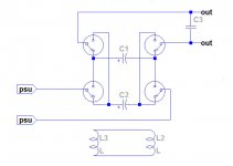
A little schematic explain better than long speech (©Napoleon)
(Yes, your both options are to be tested, i prefer the second one, as it isolate the switching frequency of the SMPS and can work with linear PSU as well.
The switching frequency of the isolation module can be made low enough to not be in the audio bandwidth. (5Hz ?))
Of course, MOS have to be used instead of a mechanical relay that was just there to figure the break before connect. ;-)
I will try-it in my preamp, so easy to have large enough caps for 10 seconds of power, considering the little consumption.
And, if I do this for all the sources, I can keep my power amp as it is. The only one device AC connected, the one with "high current pulses".
Attachments
Last edited:
I was always convinced, each time I tried-it, of the advantages to power with devices with batteries. I believe it is a matter of parasitic currents from AC lines flowing throw the grounds and cables links.
This idea is just a way to replace batteries, witch have a very short life duration, by lytic caps, much better on this aspect.
This idea is just a way to replace batteries, witch have a very short life duration, by lytic caps, much better on this aspect.
cap-switching modular integrated amp
The September 2015 Stereophile (pp. 89 - 105) has a review of a component with banks of ultracaps, and in which one bank charges while the other powers the component. Unfortunately, according to JA, the changeovers "are accompanied by a just-audible click". JA also finds a lot of things wrong with various parts of the modular design, but notes cheerfully that at least it's modular, so upgrades will be straightforward 🙂
The September 2015 Stereophile (pp. 89 - 105) has a review of a component with banks of ultracaps, and in which one bank charges while the other powers the component. Unfortunately, according to JA, the changeovers "are accompanied by a just-audible click". JA also finds a lot of things wrong with various parts of the modular design, but notes cheerfully that at least it's modular, so upgrades will be straightforward 🙂
- Status
- Not open for further replies.
- Home
- Member Areas
- The Lounge
- John Curl's Blowtorch preamplifier part II